33 - 1
Introduction
This section explains how the Powershift 6 speed
(ShiftMaster) electrical system works .
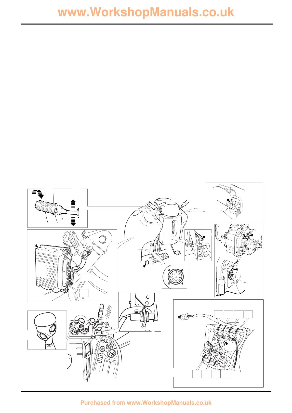
Central to the system is the ShiftMaster ECU (Electronic
Control Unit) 1. The unit receives ‘inputs’ from electrical
devices such as the gear select switch B. Depending on the
input signals the ECU ‘outputs’ energise electrical devices
such as gearbox solenoid control valves 2.
Component Identification
The ECU can be connected to diagnostics software loaded
on a laptop PC. The commincations link is facilitated via
diagnostics socket 3. See Powershift Gearbox - 6 Speed,
ShiftMaster Diagnostics - User Guide.
Note: The ECU also controls 2/4WD selection by activating
relay S. 2/4WD electrical system is not described in this
section.
Section F Transmission
9803/3280
Section F
33 - 1
Issue 2*
Electrical Connections
Powershift Gearbox - 6 Speed
ECU input devices
B Gear select switch
C Forward/Neutral/Reverse select switch
D Transmission dump switch
E Gearbox oil temperature switch
F Park brake switch
G Transmission dump relay
H Speed sensor - gearbox mounted
J Kick down switch
K Throttle switch
L Gearbox oil pressure switch
ECU output - activated devices
N In-cab warning light - high gearbox oil temperature
P In-cab warning light - low gearbox oil pressure
R In-cab master warning light and buzzer
S-Z Gearbox solenoid control valves
Note: For identification of in-cab warning lights see the
machine Operator Handbook.
 Loading...