2 - 7
Section E
Hydraulics
9803/3280
Section E
2 - 7
Issue 2*
Technical Data
Relief Valve Pressures
Loader Valve - Variable Flow
bar kgf/cm
2
lbf/in
2
Priority Relief Valve† 170 - 176 173 - 179 2450 - 2550
Auxiliary Relief Valves (A.R.V.) @ 0.5gal/min (1.9 litres/min)
Shovel Ram Head Side 170 - 174 173 - 177 2465 - 2520
Shovel Ram Rod side 306 - 314 312 - 320 4450 - 4550
† Note: Steer circuit pressure is controlled by a relief valve housed in the hydraulic steer unit (Refer to Section H Steering).
The priority relief valve housed in the loader valve must be set at 2500 lb/in
2
, this will ensure it does not interfere with the
operation of the relief valve housed in the hydraulic steer unit.
Weight:
2 Spool - TBA kg (TBA lbs)
3 Spool - TBA kg (TBA lbs)
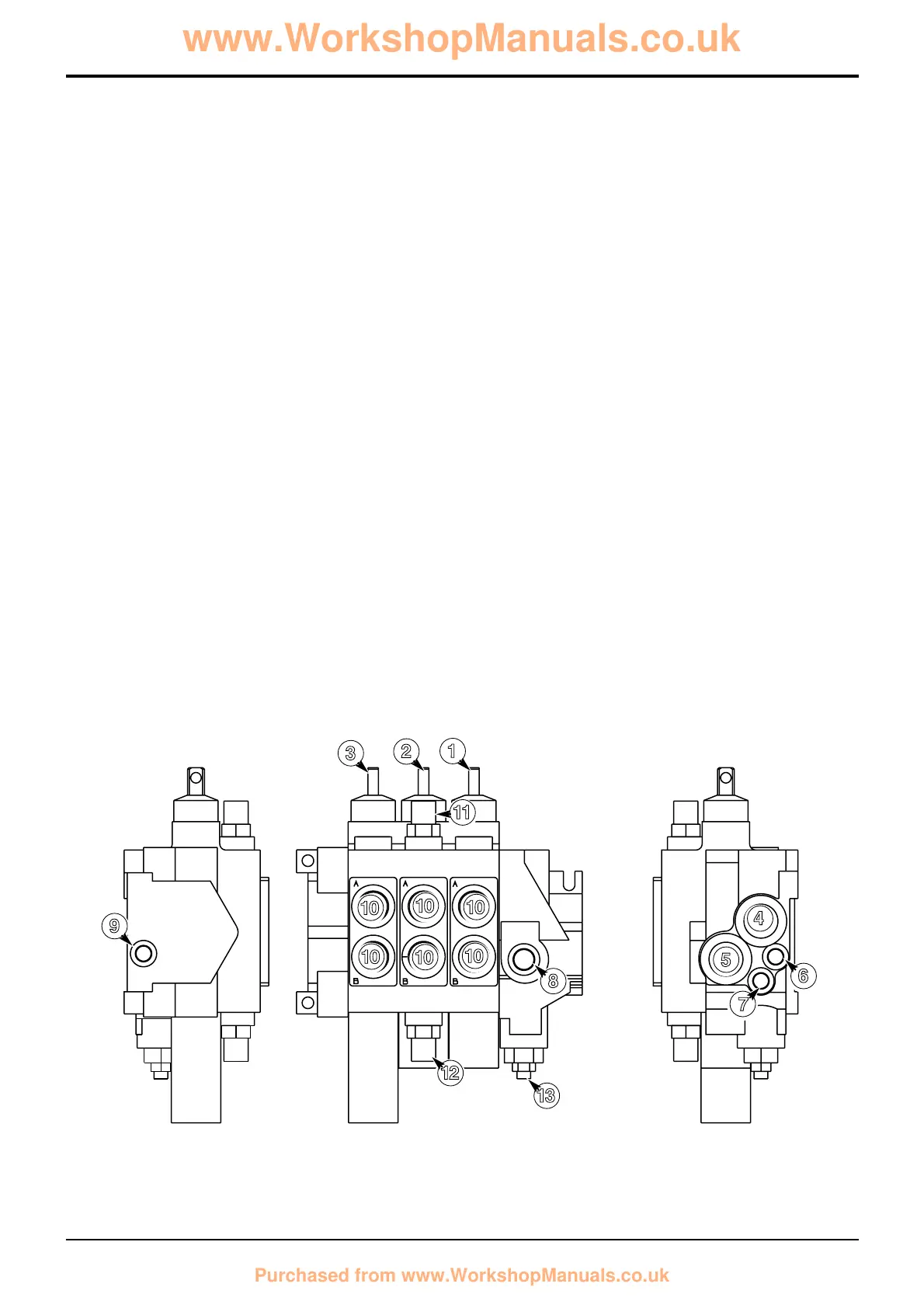
Component Key:
1 Auxiliary (optional) service
2 Shovel service
3 Arms lift service
4 Pump inlet
5 Tank port
6 Load sense port (to pump)
7 Priority load sense port (from steer unit)
8 Priority work port (to steer unit)
9 Load sense carry over port (to backhoe valve)
10 Service ports
11 Auxiliary relief valve (rod side)
12 Auxiliary relief valve (head side)
13 Priority relief valve †
 Loading...