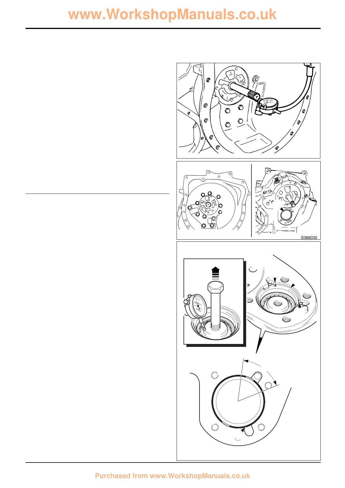
33 End Float Checking - Forward/Reverse Unit
Measure end float of forward/reverse unit shaft which
should be 0.01 to 0.16 mm (0.0004 to 0.006 in).
Note: Rotate shaft whilst measuring to seat bearings fully.
Position pointer of dial test indicator (DTI) on the chamfer of
the shaft, not the end face. This will ensure a constant
reading is given.
The forward/reverse shaft and its associated
components are manufactured using a ‘Setright’
system. Provided components are assembled correctly
the end float will be within the limits given above.
If there is no float, or too much end float, separate the
casings and check that the bearings inner and outer
cups are fitted correctly. If the forward/reverse shaft
and clutch assemblies have been dismantled check that
the assembly has been carried out correctly.
34 End Float Setting - Mainshaft
If the mainshaft, output shaft and/or associated
bearings have been renewed, the shaft end float must
be reset.
a Remove the torque converter housing and position
the gearbox to gain access to setting ring A.
b Using service tool 892/01079 tighten the setting ring
to 25 Nm (18.4 lbf ft) whilst at the same time
rotating the shaft via the output yoke (a gear must
be engaged). Do not over tighten the ring.
Overtightening will damage the bearings.
c Undo the ring a small amount to obtain a shaft end
float of 0.03 to 0.08 mm (0.001 to 0.003 in). To
measure the endfloat screw in a bolt (or service tool
892/01078) at the threaded hole in the end of the
shaft. Set up a DTI with the probe on the chamfer of
the shaft. Zero the DTI. Rotate the shaft and at the
same time pull up on the bolt, noting the reading on
the DTI. Screw the ring in or out until the end float is
correct.
d When the correct setting has been obtained, stake
the setting ring to the casing as shown at Y (see the
note below). Note that once staked the setting ring
can not be used again. If the ring is disturbed it must
be discarded and a new one used to re-set the end
float.
Note: If the slots in the setting ring fall close (within zone Z)
to the staking position Y, stake at position X instead. In this
event the ring must also be folded on one side at position Y,
fold on the side furthest away from the slot in the ring. This is
important as the ring will otherwise restrict the flow of
lubrication oil.
112-9
Section F Transmission
9803/3280
Section F
112-9
Issue 2*
Synchro Shuttle Transmission
Assembly (cont'd)
S221201
A
 Loading...