20 - 1
Section G Brakes
9803/3280
Section G
20 - 1
Issue 1
Service Procedures
Service Brakes
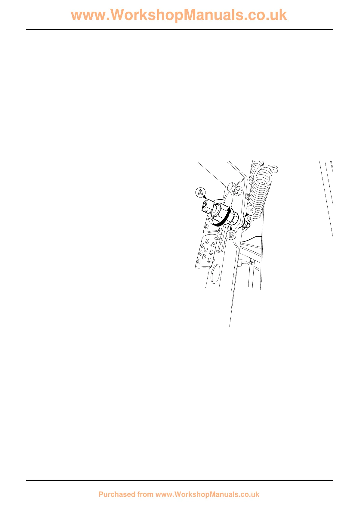
Brake Light Switch - Adjustment
1 Select the starter key switch to the ON position, do not
start the engine.
2 With the brake pedal in the return position, adjust
locknuts B and use feeler gauges to set the proximity
switch A so that there is clearance of 2mm MIN - 3mm
MAX between the end of the switch and the brake
pedal lever. The light emitting diode (L.E.D.) on the
switch should be illuminated.
3 Secure the switch in position by tightening locknuts B.
4 Depress the brake pedal and check the correct
operation of the brake lights.
Torque Settings
Item Nm kgf m lbf ft
B 29 2.95 21
A
B
B
 Loading...