127 - 2
Section F Transmission
9803/3280
Section F
127 - 2
Issue 1
Powershift Gearbox
Assembly
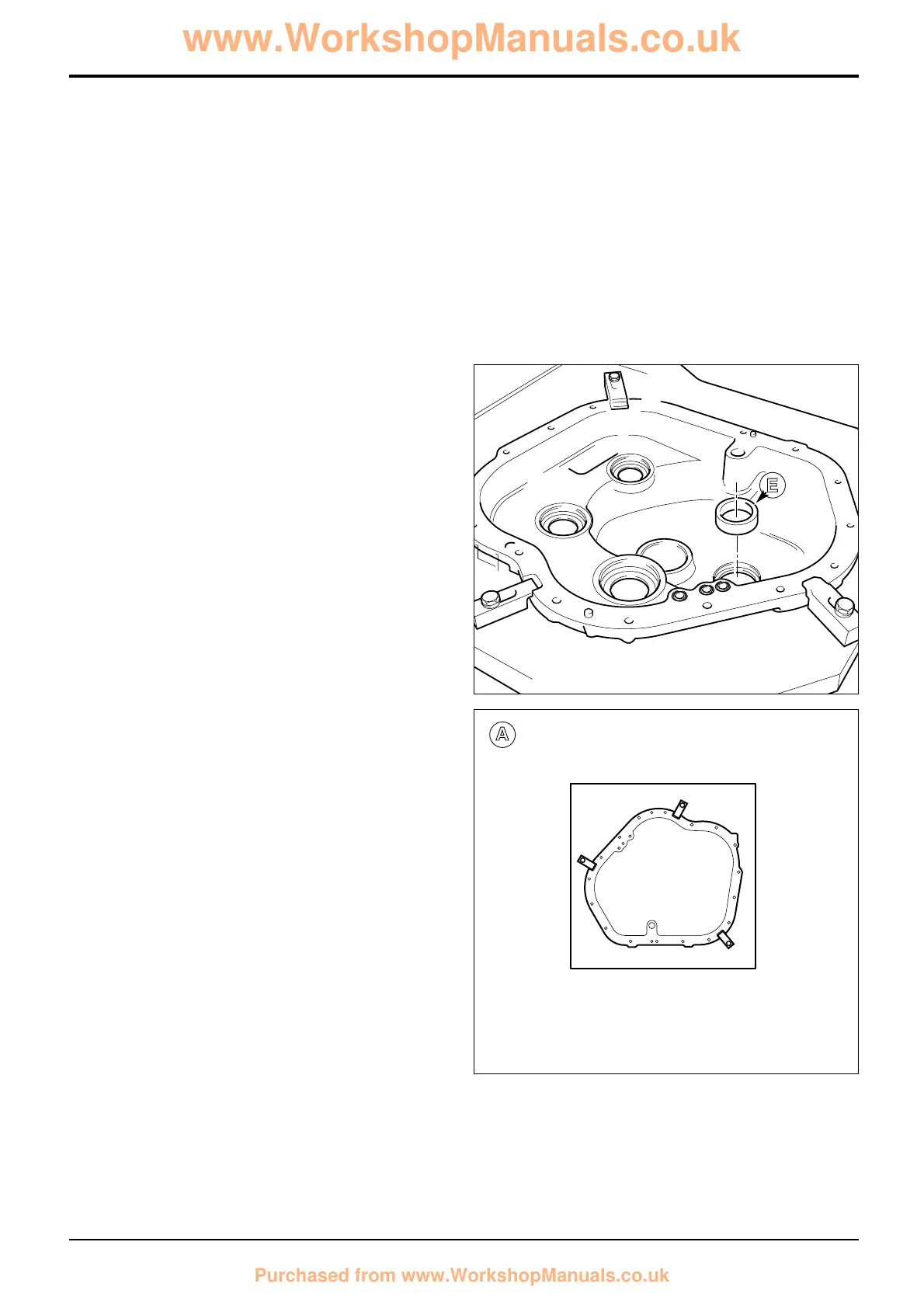
Using suitable lifting equipment locate the gearbox rear
casing in a work cradle. Clamp the casing in position at the 3
clamping points as shown at A.
DO NOT ATTEMPT TO ASSEMBLE THE GEARBOX UNLESS
IT IS SAFELY LOCATED IN A SUITABLE WORK CRADLE.
Where ‘oil’ is referred to, use new, clean transmission oil of
the correct specification for the gearbox. See Section 3,
Lubricants and Capacities.
1 Assemble the Transfer Gear/Output Shaft
Note 1: Before fitting the transfer gear/output shaft assembly
1d, fit the layshaft outer bearing cup to the casing (shown at
E).
Position the casing as shown at D.
Note 2: The inner and outer taper roller bearing assembly
(comprising double outer cup 1a, inner bearing 1c, spacer 1e
and outer bearing 1f) is a matched set. Keep all the
components together in their original relationships.
Components from another set are not interchangeable. If any
components are worn or damaged the whole assembly must
be renewed as a complete matched set.
a Make sure that you have fitted the layshaft outer bearing
cup, see Note 1 above. Fit the bearing double outer cup
1a into the casing. Note the correct way up of circlip 1b,
with the chamfer uppermost. Make sure that the circlip
locates fully in its groove as shown at B. The tangs of
the circlip must not overhang the inner diameter of the
bearing cup 1a. An incorrectly located circlip can foul
and damage the outer bearing.
b Push the inner bearing 1c onto the transfer gear/shaft
1d followed by spacer 1e.
d Locate the transfer gear assembly in the casing from
inside. Using service tool 892/01083 retain the gear in
position (shown at C). If the gear is not held in position
the bearings may be damaged during assembly.
c Using service tool 892/01084 push on the outer bearing
1f. Using service tool 892/01085 fit a new oil seal 1g.
Make sure the seal is pushed square to the housing.
e Fit yoke 1h followed by thick washer 1j and bolt 1k. Hold
the yoke using service tool 892/00812 and torque
tighten the bolt to 400 Nm (295 lbf ft).
f If applicable fit the speed sensor 11f. Make sure that the
sealing ‘O’ ring is correctly located and then torque
tighten the bolt to 28Nm (20 lbf ft).
 Loading...