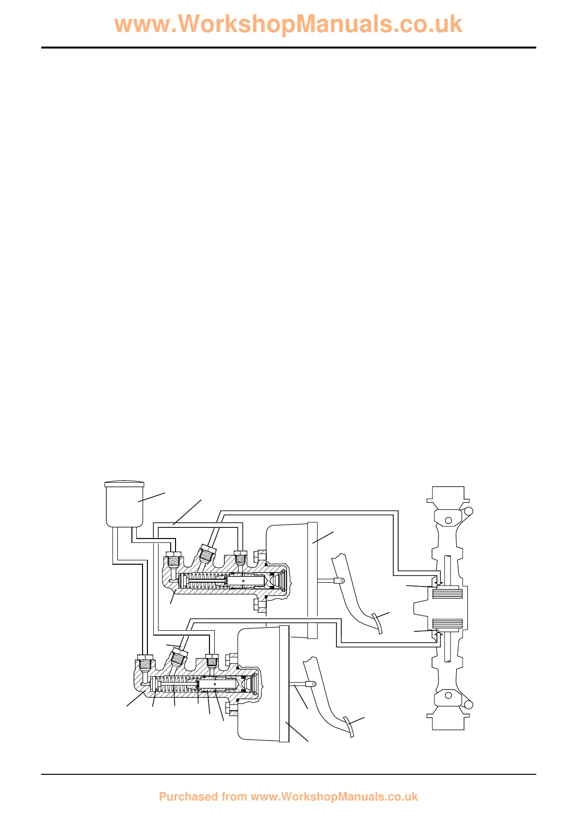
Compensating Master Cylinder
Description
Compensating master cylinders overcome the problem of
unequal wear between the right and left brake. The units
incorporate both master cylinder and compensating valve.
Each brake has its own master cylinder A, A1, brake pedals
B, B1, servo units N, N1 and associated pipework. Both
master cylinders have one common reservoir C.
Note: Dual pedal braking is applicable only to 2WS
machines. 4WS machines have a single brake pedal.
Pedals Locked - Normal Operation
When the brake pedals are pushed down (the brake pedals
are mechanically locked together), rod D pushes the plunger
E down the bore of the master cylinder. Pressurised oil
acting on centre valve seal F via valve stem G causes the
seal to close off the reservoir supply port. As the plunger
continues to move down the bore, pressurised oil flows to
the brake pack H via service port J and the associated
pipework.
Master cylinder A1 operates in the same way to feed brake
pack H1.
With valve stem G at maximum travel, further movement of
plunger E causes valve K to lift off its seat. Both master
cylinders are interconnected via bridge pipe M, therefore
hydraulic pressure in both cylinders will be equal.
If the brake packs H and H1 have worn equally, then the
amount of oil displacement between cylinders will be
minimal and the brakes will be applied evenly.
Pedals Locked - Compensating Operation
When the brake pedals are pushed down (the brake pedals
are mechanically locked together), actuation of the brake
packs H and H1 is as described in Pedals Locked - Normal
Operation. If however, the brakes have not worn equally,
then the amount of fluid displaced from each master
cylinder will vary and some form of compensation is
required.
Pedal application moves plungers E down the bores of
master cylinders A and A1. Linings of brake H are brought
into contact before the linings of brake H1 because they
have not worn as severely.
If further displacement took place at the linings, brake H
would be applied before brake H1. Therefore master
cylinder A begins to compensate for master cylinder A1.
Fluid is displaced from A to A1 via bridge pipe M until the
pressures are equalised. In this condition both
compensating valves are open and both brakes are applied
evenly.
Pedals Unlocked - Normal Operation
When a single brake pedal is pushed down, rod D pushes
the plunger E down the bore of the master cylinder.
Pressurised oil acting on centre valve seal F via valve stem
G causes the seal to close off the reservoir supply port. As
the plunger continues to move down the bore, pressurised
oil flows to the brake pack H via service port J and
associated pipework, thus braking one wheel only.
With valve stem G at maximum travel, further movement of
plunger E causes valve K to lift off its seat. Fluid is
displaced through drillings P from the active cylinder A via
bridge pipe M to passive cylinder A1. Valve K1 in the
passive cylinder is held on its seat by the displaced
pressurised fluid.
3 - 1
Section G Brakes
9803/3280
Section G
3 - 1
Issue 1
Basic System Operation
 Loading...