Transmission
Electrical Connections
Section F Section F
9808/3270
Issue 1
32 - 9
32 - 9
Powershift Gearbox - 4 Speed (cont’d)
(Machines up to 933756)
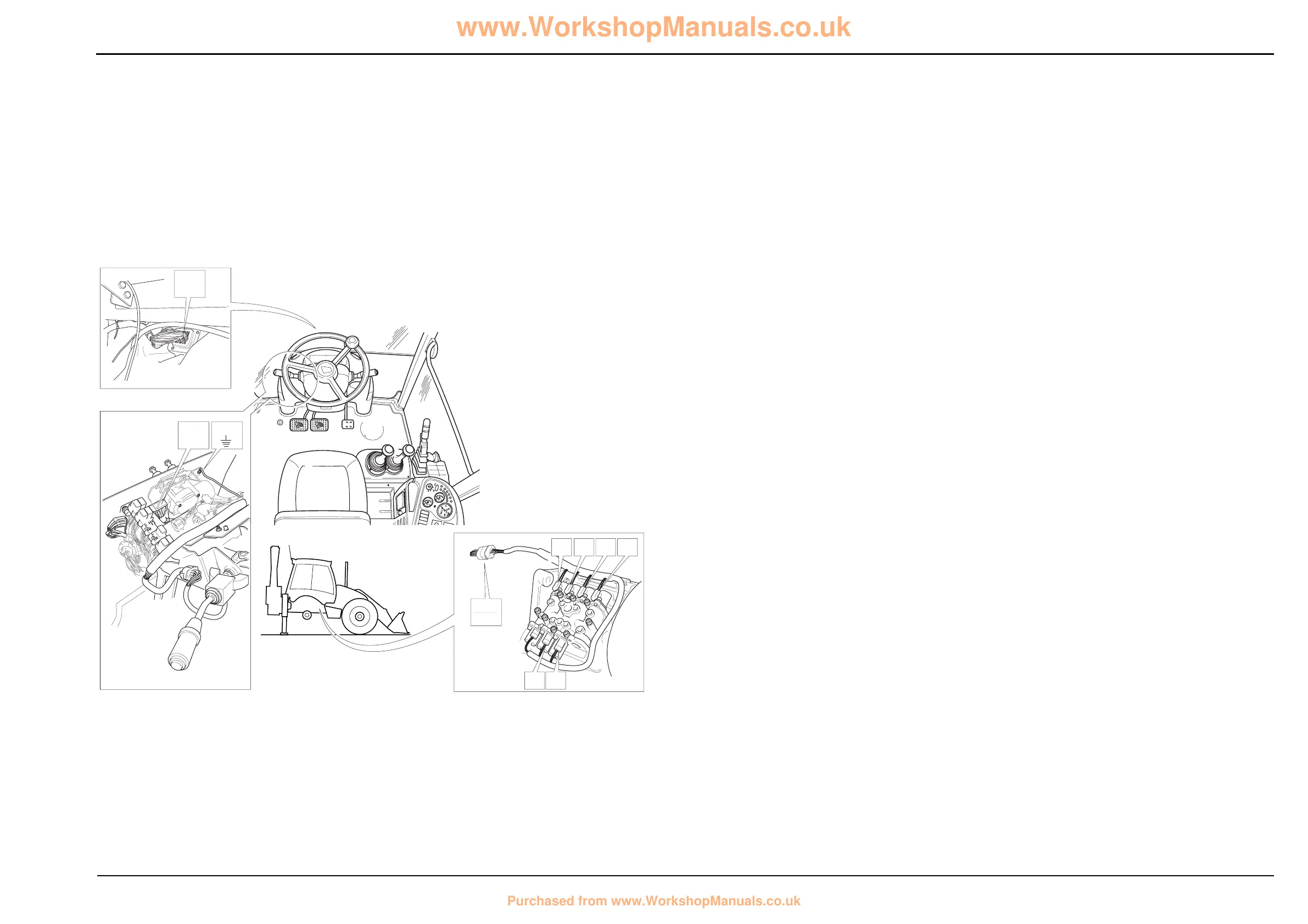
Electrical Connections - Wires and Connectors
Gearbox Solenoid Actuation
For relay activation see previous page.
Component Key (solenoid activation):
The following key identifies the component connectors on
the diagrams opposite. Note that the wires coloured green
show the electrical ‘feed to earth’ for the gearbox mounted
solenoids. Live feed (wires coloured red) to the relay
switches is supplied via the dump relay FG. Note that the
destination for wire 107 from splice SS is shown on the relay
actuation diagram (previous page).
h1 Harness - 721/10940 Front console
h2 Harness - 721/10942 Link
h5 Harness - 721/10939 Gearbox
Note: For harness drawings see Section C.
Connectors (h1)
FA h1 î h2
FB1 Earth point
FD1 Forward high/low relay
FD2 Forward relay
FE1 Reverse high/low relay
FE2 Reverse relay
FF1 Interlock relay
FF2 Mainshaft/layshaft relay
FG Transmission dump relay
X For wire 107 destination see Relay Actuation diagram
Connectors (h2)
LA h1 î h2
LC h2 î h5
Connectors (h5)
C10 h5 - h2
C20 Gearbox solenoid U (labelled E)
C30 Gearbox solenoid T (labelled F)
C40 Gearbox solenoid Y (labelled G)
C50 Gearbox solenoid Z (labelled H)
C60 Gearbox solenoid W (labelled I)
C70 Gearbox solenoid V (labelled J)
Splices (h1)
SS
ST
Splices (h2)
SC
Splices (h5)
SA
Earth Points
Faults may be caused by poor earth connections. Although
earth connections are shown opposite, it must be
remembered that the cab assembly is earthed via further
earth strap and cable connections. For details of these
connections see Section C, Machine Earth Connections.
 Loading...