40 - 1
Removal and Replacement
Removal
1 Park the machine on firm level ground, engage the
parking brake and set the transmission to neutral.
Lower the loader arms to the ground.
2 Position the carriage in the central protruding travel
position at 150 mm (6 in) from end of the rail, rest the
bucket on the ground and remove the starter key.
3 Operate control levers to vent hydraulic pressure.
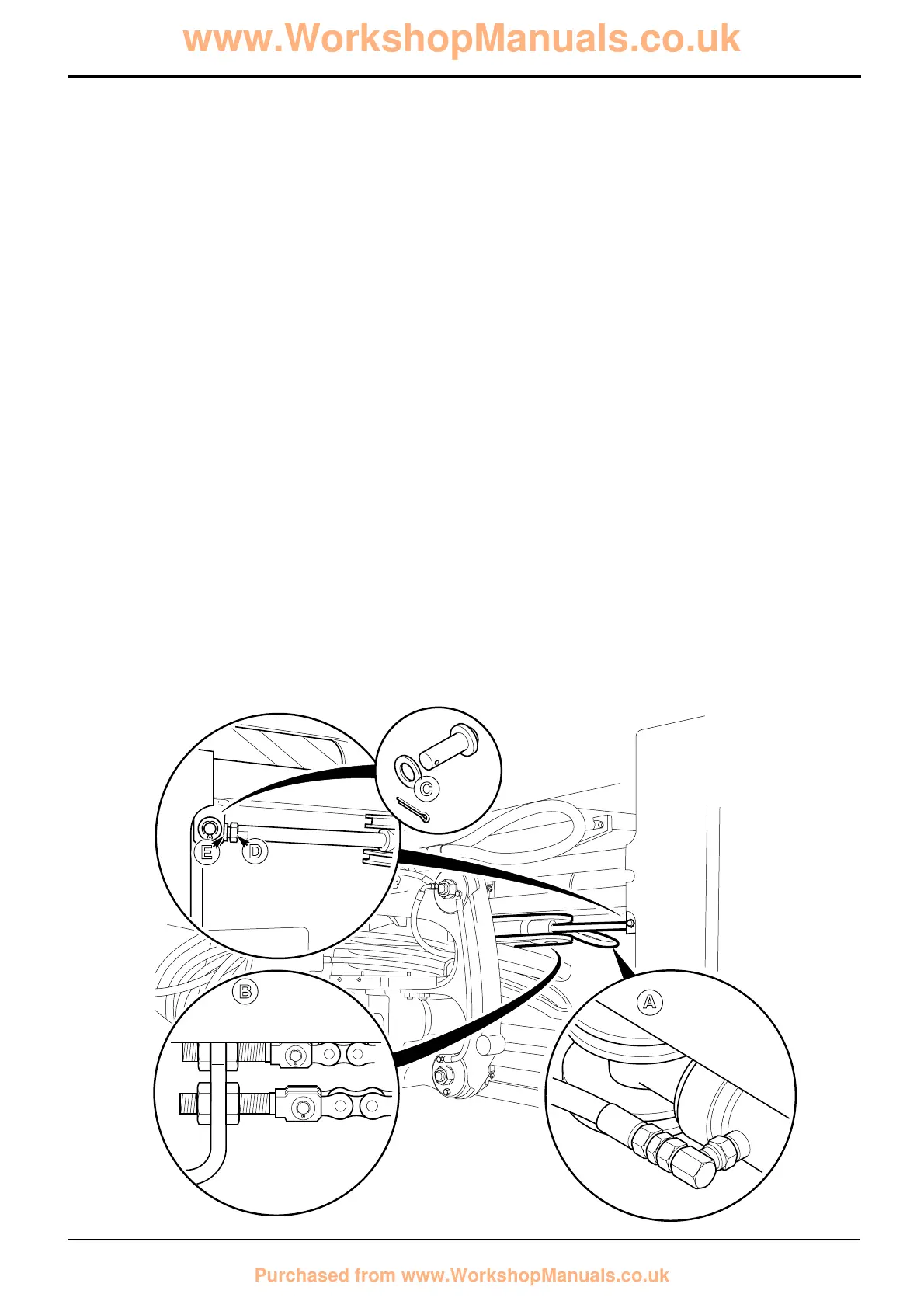
4 Disconnect hydraulic hoses A and plug.
5 Disconnect all four chains at adjusters B and disengage
chains from ram pulleys.
6 Remove pin C from one end and support the ram.
7 Remove pin C from opposite end, withdraw ram.
Replacement
1 Locate the ram at one end with pin C. Adjust the ram
eye end so the the opposite end of the ram aligns with
mounting bracket.
2 Secure the opposite end of the ram in position with pin
C.
3 With a spanner on the rod end flats D adjust the rod so
that the ram eye end engagement is equal at each end
of the ram. Lock eye ends in position with nut E.
4 Reconnect the hydraulic hoses.
5 Locate the chains around the applicable ram pulleys.
Reconnect chains and adjust as required, refer to
Service Procedures, Power Sideshift - Chain
Adjustment.
Section B Body & Framework
9803/3280
Section B
40 - 1
Issue 1
Power Sideshift Ram
C
A
B
E
D
A326850
 Loading...