Hydraulic Pump - Variable Flow
Pressure/Flow Regulator Valve
The pressure and flow regulator valve assembly is mounted
to the pump. The valve maintains the pump pressure and
flow rate in accordance with demand at the service valve
blocks.
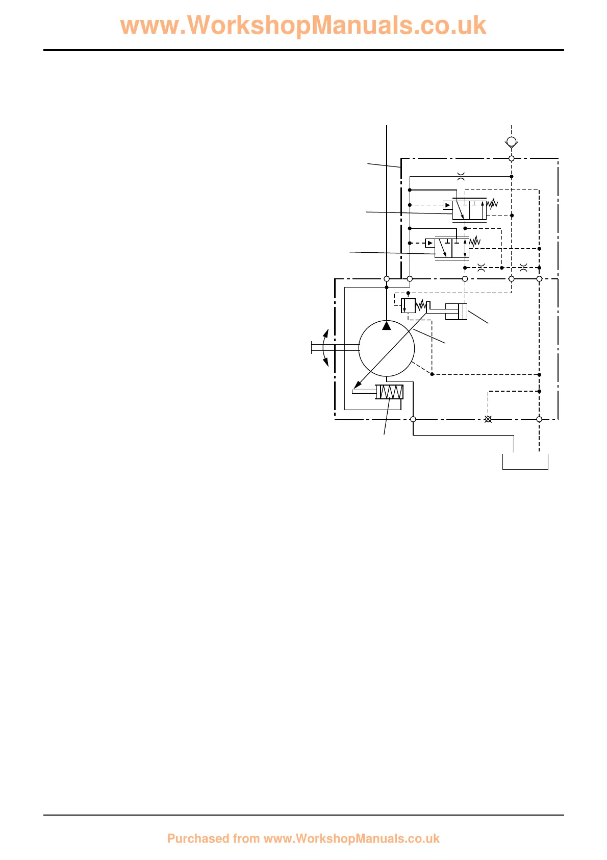
Load Sensing - Stand-by Position
Stand-by is when the machine is running but the control
levers are in neutral position, i.e. no implements are being
used. There is no pressure or flow demands on the pump,
therefore there will be no pressure signal .
With the engine switched off, spring 1 holds swashplate 2 at
the maximum angle. When the engine is started and the
pump begins to turn, oil begins to flow and pressure builds in
the closed centre hydraulic system.
Valve 5 houses a flow regulator spool 4 and pressure
regulator spool 3. Pressure which is building in the closed
centre system is sensed at port P of the regulator valve. The
increasing pressure pushes flow compensating spool 4 up
against its spring 6. This movement creates a flow path from
port P to port A. Oil now flows from the flow regulator valve
(via port A) to swashplate control piston 7.
The control piston now moves the swashplate 2 towards its
minimum angle. As the piston moves towards its full travel
position, cross-drilled holes 8 are uncovered allowing oil to
drain.
The cross-drilled holes limit the travel of the control piston -
when the holes are exposed, pump flow is insufficient to
make up for leakage through the holes and maintain the
pressure behind the control piston. Therefore the piston
moves back to partially cover the cross holes thus
maintaining enough flow to cater for normal system leakage
whilst establishing a system stand-by pressure (see
Technical Data for pressure).
5 - 5
Section E
Hydraulics
9803/3280
Section E
5 - 5
Issue 1
Circuit Descriptions
 Loading...