Steering
9803/3280 Issue 1
Steer Unit Operation
- 4 Wheel Steer Machines
2 Wheel Steer Mode
- Right Turn
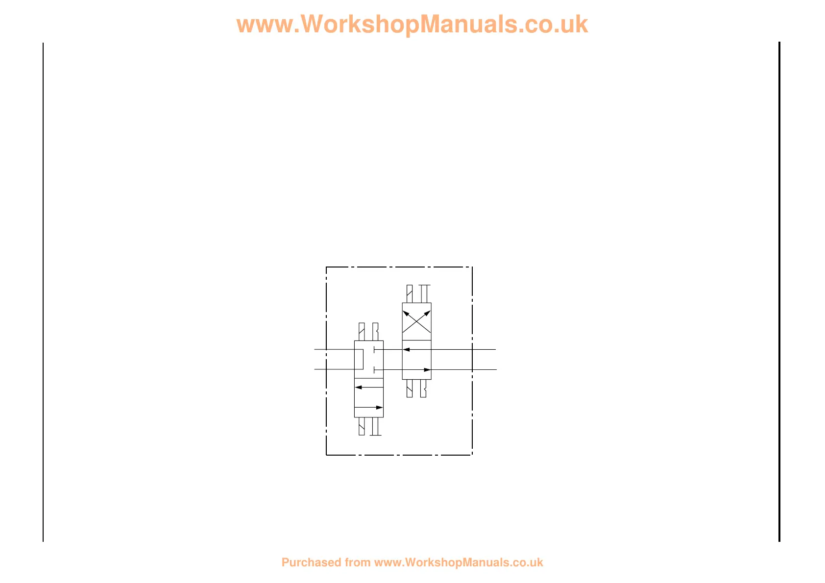
The illustration shows the flow through the steering
unit in a right hand turn condition. The operation is
identical to that described for the 4 wheel steer
mode, except the steer mode control valve X
iscolates the oil flow to the rear power track rod
ram 41, consiquently the rotor lobes pump oil out
to the front power track rod only. The rear wheels
are held in the straight ahead position by the
locked-up oil in the rear power track rod ram.
Component Key:
A Inner Spool
B Outer Spool
D Stator
LS Load Sensing Port
X Steer Mode Control Valve
40 Front Power Track Rod Ram
41 Rear Power Track Rod Ram
43B Relief Valve
43C Non-Return Valve
In 2 wheel steer mode the spools of the steer mode
control valve X are configured as shown.
4 - 13 4 - 13
Circuit Descriptions
Section H Section H
 Loading...