Excavator Valve
Precision Control (Servo) (continued)
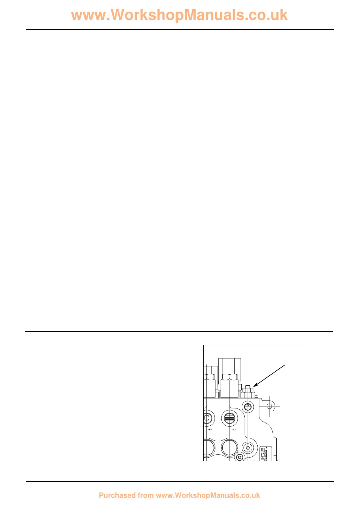
(Machines up to serial no. 931159)
Load Sense (Isolator Compensator) Valve
Operation
No service is selected (all spools in neutral)
With the spools in the neutral position oil from the pump P
flows to each spool and is dead ended. This generates
sufficient pressure (about 20bar) to overcome the spring E1
and oil flows across the bypass compensator spool
assembly E to tank. Note that oil from the pump also flows
into the ‘auxiliary pump gallery’ 1. Oil from the ‘bridge
galleries’ 3 is vented to tank via a groove in the main spool S.
8 - 16
Section E
Hydraulics
9803/3280
Section E
8 - 16
Issue 2*
Circuit Descriptions
Spool at point of operating a service
Pressure from the load on ram R enters the bridge gallery 3
via the service port 4. Compensator check valve H is held
down on its seat preventing the load moving. At the same
time the isolator spool U lifts and allows oil from the auxiliary
pump gallery 1 to flow into the load sense gallery 2. Oil
pressure builds in gallery 1 and the bypass compensator
spool E begins to close under the action of the oil and spring
(E1) pressure. This causes the pump pressure to rise to a
new value as follows:
Pump pressure = Pressure in load sense gallery 2 + pressure
from spring E1.
When the pressure in load sense gallery 2 reaches the load
pressure, isolator spool U moves down and closes off the
auxiliary pump gallery 1 from load sense gallery 2. If the load
pressure subsequently rises or falls, the isolator spool moves
due to pressure imbalance and maintains the pressure in the
load sense gallery 2 at the same pressure as the load
pressure. The pressure in the load sense gallery 2 always
Spool fully operating a service
As the spool S is moved further oil from the pump is diverted
into the central gallery 5. If the pump pressure has risen
sufficiently (to a pressure equal to the load + spring pressure
E1) then check valve H moves up off its seat and allows oil
to flow into bridge gallery 3, and out to the ram R via service
port 4. Exhaust oil from the other side of ram R is diverted to
tank.
bleeds to tank, again causing pressure imbalance and the
isolator spool to move, allowing the pressure in the gallery to
be ‘topped up’. This ensures that ‘pressure balance’ is
always maintained.
It must be noted that the load sense gallery 2 is connected to
all load sense valves (one for each service). The pressure in
the gallery 2 will always be equal to the highest load from
any of the backhoe services. The maximum load sense
pressure is regulated by the load sense drain regulator/relief
valve F (see below).
Any load on the service ram R is held by the main spool S.
Oil is also vented to tank from the load sense gallery 2 via
the load sense drain regulator/relief valve F (see below).
F
*
 Loading...