83 - 7
Section F Transmission
9803/3280
Section F
83 - 7
Issue 1
Front Axle - SD70
S256120
C
B
S256110
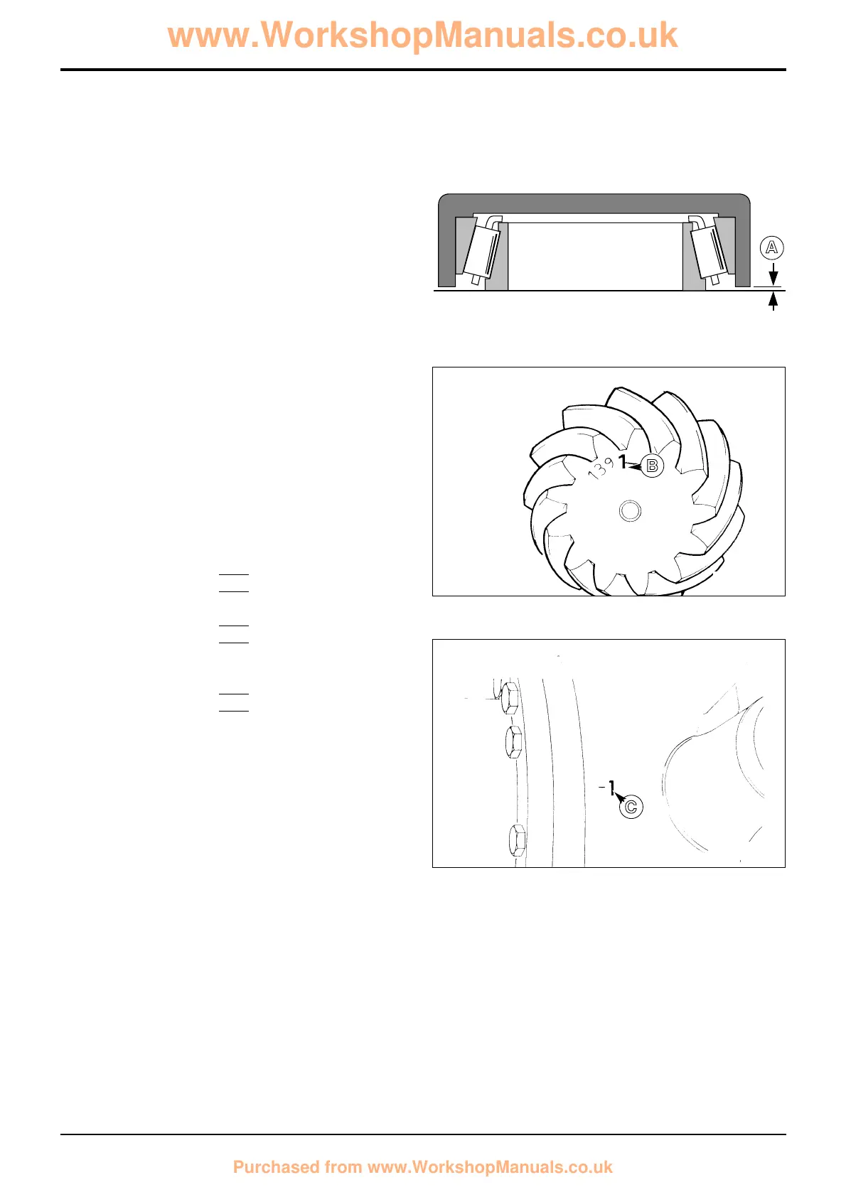
Pinion Depth Setting
1 Place new pinion head inner bearing assembly on a flat
surface and position service tool 892/00174 over the
bearing. Measure gap A (e.g. 0.20 mm) and add this to
the cup depth stamped on the tool (e.g. 30.01 mm) to
obtain the bearing depth.
2 From the face of the pinion, obtain the etched deviation
figure B (e.g. + 2) which is in units of 0.01 mm. If
positive, add this to the bearing depth; if negative,
subtract from the bearing depth.
3 Obtain the deviation figure C (e.g. - 1) stamped on the
differential housing bolt flange. If negative, add to
bearing depth; if positive, subtract from bearing depth.
4 Subtract the total of the above figures from the
standard value of 31.19 mm. The result will be the
thickness of shims required behind the pinion head
bearing cup.
Example (all dimensions in millimetres)
Cup depth 30.01
Gap A +0.20
Bearing depth 30.21
Pinion deviation B (+ 2) +0.02
Housing deviation C (- 1) +0.01
Total 30.24
Standard value 31.19
Less Total above 30.24
Shim Thickness 0.95
Note: In the event that the setting data stamp has been
ommited from the drivehead casing, adopt the following
setting procedure:
Revise the shim pack size by the difference in setting height
marked on the old and new crownwheel pinion sets.
A184400
A
 Loading...