Excavator Valve
Precision Control (Servo)
(Machines up to serial no. 931159)
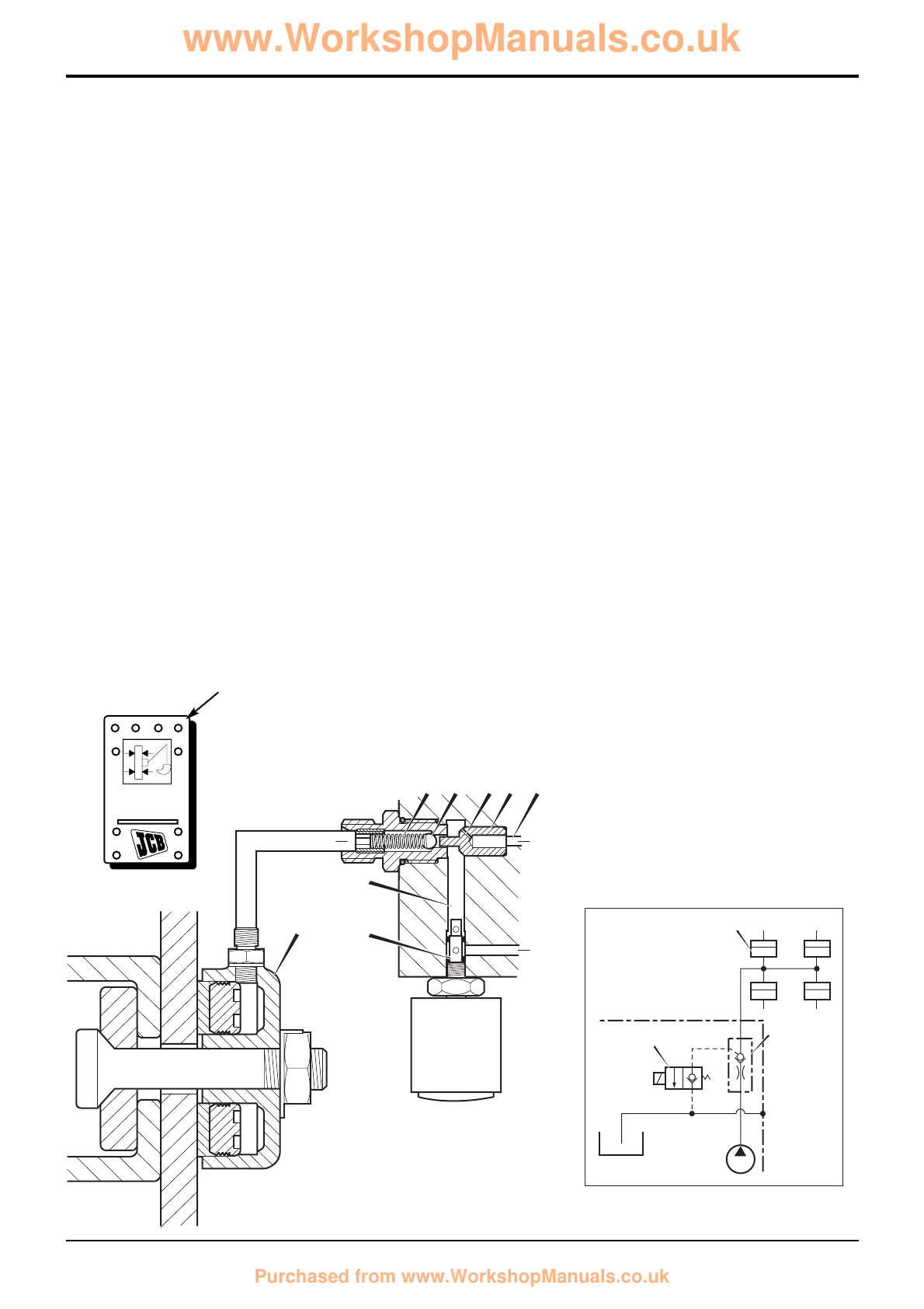
Hydraclamp Valve Operation
When the backhoe is being used for excavating duties, the
kingpost assembly must be 'clamped' to the sideshift
rearframe.
The hydraclamp control valve assembly (items G, D and C) is
positioned in the front face of the excavator valve block and
is connected directly to the parallel gallery B. The valve
operates in conjunction with solenoid valve E located in the
bottom of the excavator valve block.
1 - Clamps Pressurised
When the hydraclamp switch A is in the OFF position (not
pressed), the solenoid valve E is de-energised. The solenoid
valve in this de-energised state blocks the exhaust path from
the galleries B and F to the drain port T (tank).
When an excavator service is operated, pressure is
generated in parallel gallery B, this pressurised oil moves
piston C which pushes ball D off its seat against the force of
spring G. The oil flows through restrictor H, past the ball and
out to the hydra-clamps 62.
2 - Clamps Released - Precision Control Machines Only
To enable clamps release, the hydraclamp switch A must be
in the ON position and an excavator service must be
operated.
With the hydraclamp switch A in the ON position (pressed
down), the solenoid valve E is energised. Pressure resulting
from the operation of an excavator service moves piston C
which pushes ball D off its seat.
With ball D lifted and the solenoid valve in its energised
state, oil from the hydra-clamps is vented through the clamp
valve and gallery F to the drain port T (tank).
Also, pressure resulting from the operation of an excavator
service passes through restrictor H. The oil takes the path of
least resistance and is vented via gallery F to the drain port T
(tank).
Restrictor H ensures that only a small amount of oil from
gallery B is dumped back to tank.
3 - Clamps Locked Up
If no service is being operated, pressure in the parallel gallery
falls to that of the neutral circuit and the force of spring G is
sufficient to keep the ball D seated. Pressure is therefore
trapped in the line to the clamps, maintaining the excavator
end in a securely clamped condition.
8 - 17
Section E
Hydraulics
9803/3280
Section E
8 - 17
Issue 2*
Circuit Descriptions
 Loading...