2 - 8
Section E
Hydraulics
9803/3280
Section E
2 - 8
Issue 2*
Technical Data
Relief Valve Pressures
Excavator Valve - Fixed Flow
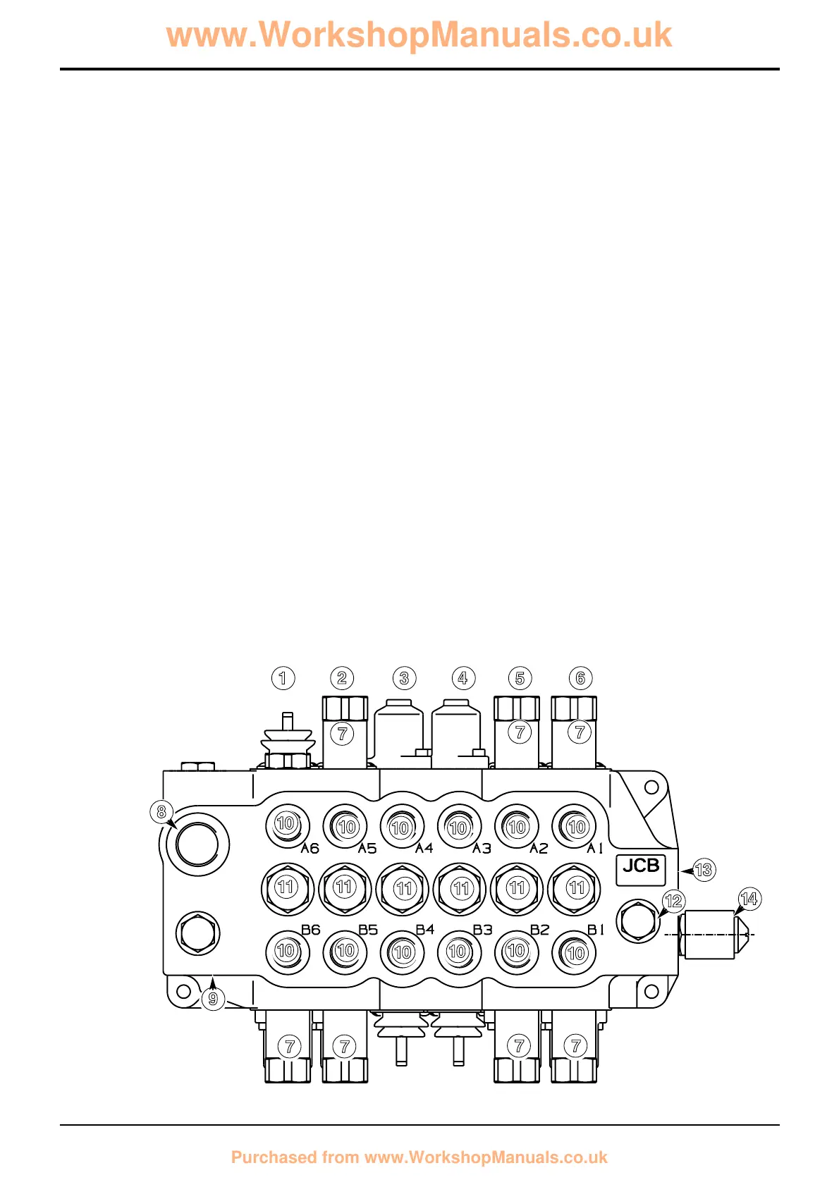
Component Key:
1 Bucket crowd
2 Dipper †
3 Stabiliser
4 Stabiliser
5 Boom †
6 Slew
7 Auxiliary relief valve
8 Tank port
9 High pressure carry-over (HPCO) port
10 Service ports
11 Load hold check valve assemblies
12 Make-up check valve assembly
13 Inlet port
14 Hydraclamp solenoid
bar kgf/cm
2
lbf/in
2
Boom Ram Head Side 248 - 255 253 - 260 3600 - 3700
Boom Ram Rod Side 345 - 352 351 - 358 5000 - 5100
Bucket Ram Head Side
Centremount (17' , 15’ 6” backhoe - except knuckle) 310 - 317 316 - 323 4500 - 4600
Centremount (14' backhoe, 15’ 6” backhoe with a knuckle fitted) 248 - 255 253 - 260 3600 - 3700
Sideshift 248 - 255 253 - 260 3600 - 3700
Bucket Ram Rod Side (Machines with Rockbreaker only) 248 - 255 253 - 260 3600 - 3700
Dipper Ram Head Side 248 - 255 253 - 260 3600 - 3700
Dipper Ram Rod Side 248 - 255 253 - 260 3600 - 3700
Slew Left and Right 262 - 269 267 - 274 3800 - 3900
Weight:
44 kg (97 lbs) - Centremount
46 kg (101 lbs) - Sideshift
Note: Instructions for pressure testing and adjustment are described in Service Procedures, Loader Valve - Pressure
Testing.
† System shown is for JCB plus pattern and JCB diagonal pattern. For ISO system, the boom and dipper spools change
position, i.e. boom is position 2 and dipper is position 5. The bottom ARV from spool 5 will also be swapped with the
bottom ARV from spool 2.
A401470
1
0
0
0 0
0
0
!
!
! !
!
!
0
0
0
0
0
7
7 7
7
7
7
7
2 3 4 5 6
8
@
£
9
$
0
 Loading...