20 - 3
Proximity Switch - Setting
!
WARNING
Raised loader arms can drop suddenly and cause
serious injury. Before working under raised loader arms,
fit the loader arm safety strut.
GEN 3-2
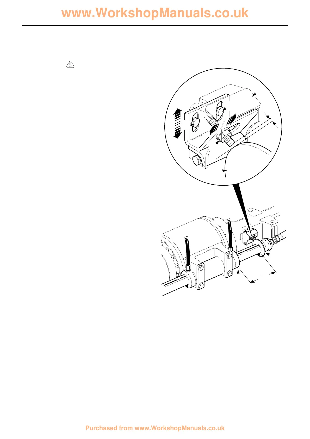
Note: The proximity switch setting procedure is the same for
both the front and rear axles. The illustration shows a typical
rear axle.
1 Align the wheels in the straight ahead position. Check if
straight ahead by measuring the steering ram position.
Set the steering so that dimension X is equal both
sides.
2 Remove the proximity switch cover C.
3 With the starter switch on, loosen the proximity switch
lock nut D and slide the switch in line with the target
disc A.
4 Loosen the bracket fixing bolts E and adjust the
assembly up or down to bring the switch to the centre
of the target disc. Tighten the fixing bolts E.
Make sure the light emitting diode (L.E.D.) is not
illuminated (if it is then screw the switch out).
Now screw the proximity switch towards the target disc
until the light emitting diode (L.E.D.) on the switch
illuminates. Add a further 1 to 1.5 turns of the locknut.
Tighten the locknut.
Section H Steering
9803/3280
Section H
20 - 3
Issue 1
Service Procedures
 Loading...