Electrics
Technical Data
Section C Section C
9803/3280
Issue 3*
2-3
2-3
Relays
4 speed Powershift / Synchro Shuttle
The relays listed below are located in the side console
underneath cover A.
1 Ignition 1
2 Hammer
3 Auxiliary (jaw bucket)
4 Main lights
5 Engine run
6 Hydraulic speed control (HSC)
7 Buzzer (from serial no. 933757 only)
8 Buzzer
9 Ignition 2
10 Front working lights
11 Rear working lights
12 Direction indicator
13 Neutral start
14 Rear horn
15 Parking brake warning light
16 Air conditioning compressor
17 Parking brake (from serial no. 933757 only)
6 speed Powershift (Shiftmaster)
The relays listed below are located in the side console
underneath cover A.
1 Ignition 1
2 Hammer
3 Auxiliary (jaw bucket)
4 Main lights
5 Engine run
6 Hydraulic speed control (HSC)
7 Buzzer
8 Buzzer
9 Ignition 2
10 Front working lights
11 Rear working lights
12 Direction indicator
13 Neutral start
14 Rear horn
15 Parking brake warning light
16 Air conditioning compressor
17 Parking brake
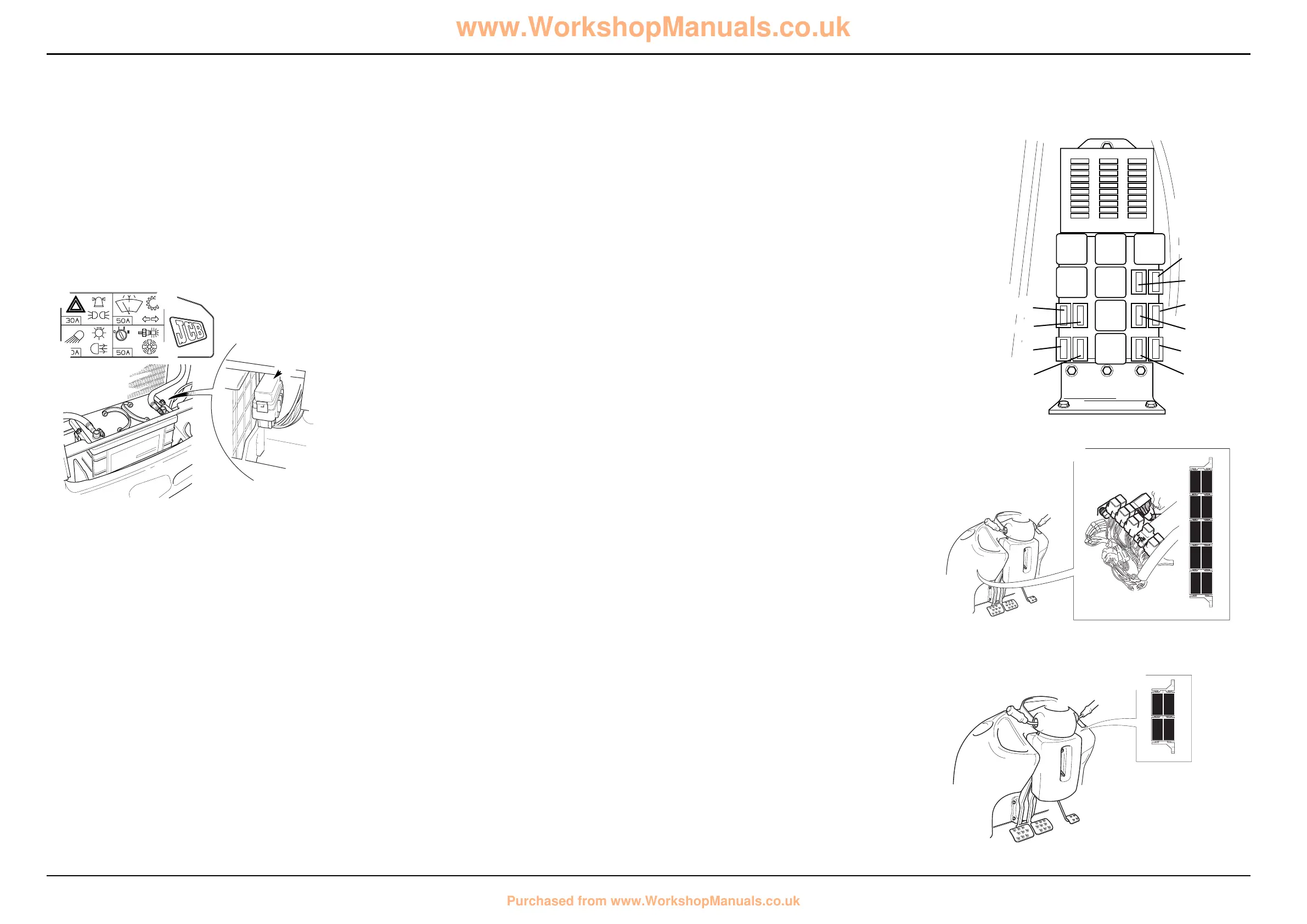
The relays listed below are located in the front console as
shown at C.
FD1 Forward HI/LO
FD2 Forward
FE1 Reverse HI/LO
FE2 Reverse
FF1 Interlock
FF2 Drive
FG1 Blank
FG2 Transmission dump
FH1 Auto 2WD
FH2 4WB
The relays listed below are located in the front console as
shown at D.
FG1 Reverse Alarm
FG2 Transmission dump
FH1 2WB
FH2 Brake lights
Note: Relay base positions may vary from those shown at D.
Compare wire numbers on the relevant front consloe
harness drawing to confirm relay identification
A
BC
10
9
8
7
6
5
4
3
2
1
10
9
8
7
6
5
4
3
2
1
10
9
8
7
6
5
4
3
2
1
1
2
3
4
5
6
7
8
9
0
!
@
£
$
%
^
&
396500
Fuses and Relays (continued)
Link Box Fuses
To further protect the machine wiring harnesses and
electrical circuits, a fuse link box is fitted to the battery, as
shown at B. Remember to check the main circuit fuses as
well as the link box fuses shown on this page.
1 Hazard warning lights, Beacon, Lights 30 Amp
2 Wash/Wipe, Transmission, Indicators 50 Amp
3 Work lights, Fog Lights, Brake lights 50 Amp
4 Ignition, Heater, Thermostart 50 Amp
A405390
FD2
FD1
FE2
FE1
FF2
FF1
FG 2
FG 1
FH2
FH1
A405400
FG 2
FG 1
FH2
FH1
www.WorkshopManuals.co.uk
Purchased from www.WorkshopManuals.co.uk
 Loading...