1-1
SECTION 1
DISASSEMBLY
1.1 HOW TO REMOVE THE MAJOR PARTS
1.1.1 Introduction
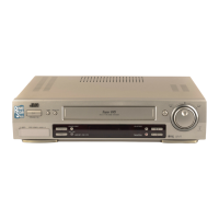
This set is a double-deck video recorder integrating a Mini DV
deck and a VHS deck. Its internal structure is divided into three
sections that include the power supply, VHS and DV sections.
Therefore, the removal of major parts will also be described
under three separate sections as listed below.
1. COMMON section
2. VHS section
3. DV section
1.2 HOW TO READ THE DISASSEMBLY AND ASSEMBLY
3. DV section
1. COMMON section
2. VHS section
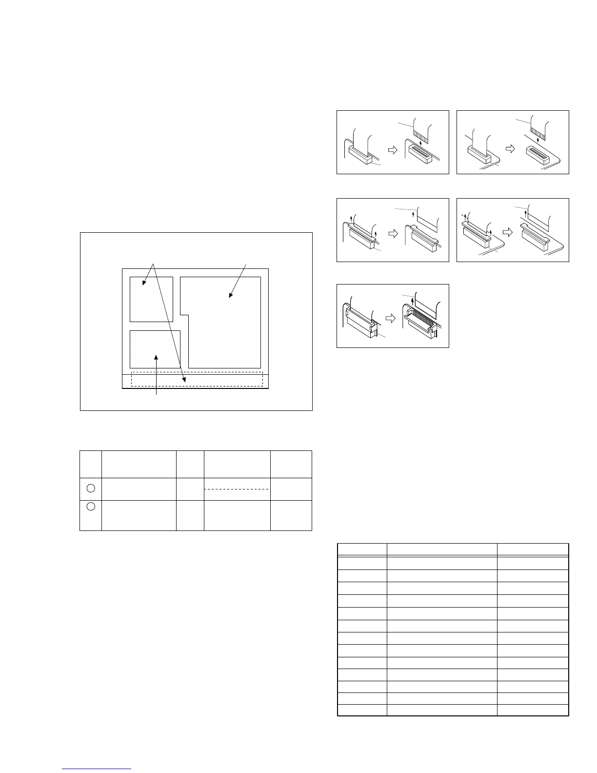
< TOP VIEW >
(1) Order of steps in Procedure
When reassembling, perform the step(s) in the reverse order.
These numbers are also used as the identification (location) No.
of parts Figures.
(2) Part name to be removed or installed.
(3) Fig. No. showing procedure or part location.
(4) Identification of part to be removed, unhooked, unlocked,
released, unplugged, unclamped or unsoldered.
P= Spring, W= Washer, S= Screw, L= Locking tab, SD= Solder,
CN**(WR**)= Remove the wire (WR**) from the connector
(CN**).
Note:
• The bracketed ( ) WR of the connector symbol are as-
signed nos. in priority order and do not correspond to
those on the spare parts list.
(5) Adjustment information for installation
Fig. 1-1-1
§§ §§ §
(1) (2) (3) (4) (5)
Step/
Loc No.
Fig. No.
Point NotePart name
Top cover, Bracket COM1
4(S1), 3(S2), 2(L1), (L2)
2(S3)
1
—
Front panel
assembly
COM2 8(L3),
CN7507(WR1),
CN3011(WR2)
<Note
1,2,3,4>
2
1.3 DISCONNECTION OF CONNECTORS (WIRES)
CONNECTOR
FPC
CONNECTOR
FPC
Fig. 1-3-1 Fig. 1-3-2
Fig. 1-3-3 Fig. 1-3-4
CONNECTOR
FPC
Fig. 1-3-5
CONNECTOR
FPC
CONNECTOR
FPC
1.4 SCREWS USED CABINET COMPONENTS AND
BOARD ASSEMBLIES
Table 1-4-1 below shows the symbols, shapes, colors and
part numbers of screw that are used in the cabinet compo-
nents and board assemblies and are appearing in the disas-
sembling/reassembling diagrams in this manual.
When screwing them again in reassembling, be sure to use
them correctly referring to the following table.
Notes:
• Screw that are asterisked (marked with*) in the shape col-
umn are fixed with screw lock agent. If such the screw is
once removed, never use it again.
• The Screw symbols are assigned nos. in priority order and
do not correspond to those on the spare parts list.
SYMBOL PARTS NO. COLOR
S1 QYTDST3006R SILVER BLACK
S4 QYTDSF2606Z GOLD
S8 PQ21623-2-5 GOLD
S5 QYTDST3006Z GOLD
S2 QYTDST3006M BLACK
S6 QYTDSF3008M BLACK
S3 QYTDSF3010Z GOLD
S7 QYTDST2610Z GOLD
S11 QYTDSP2004Z GOLD
S12 QYTDST2004Z GOLD
S13 YQ43893 SILVER
S9 PQ40413 BLACK
S10 LP40700-001A BLACK
Table 1-4-1
 Loading...