1-2
1.5
HOW TO REMOVE THE MAJOR PARTS <COM section>
1.5.1 Disassembly flow chart
This flowchart shows the disassembly procedure for the ex-
terior parts and electrical parts.
Basically, reverse this procedure when assembling them.
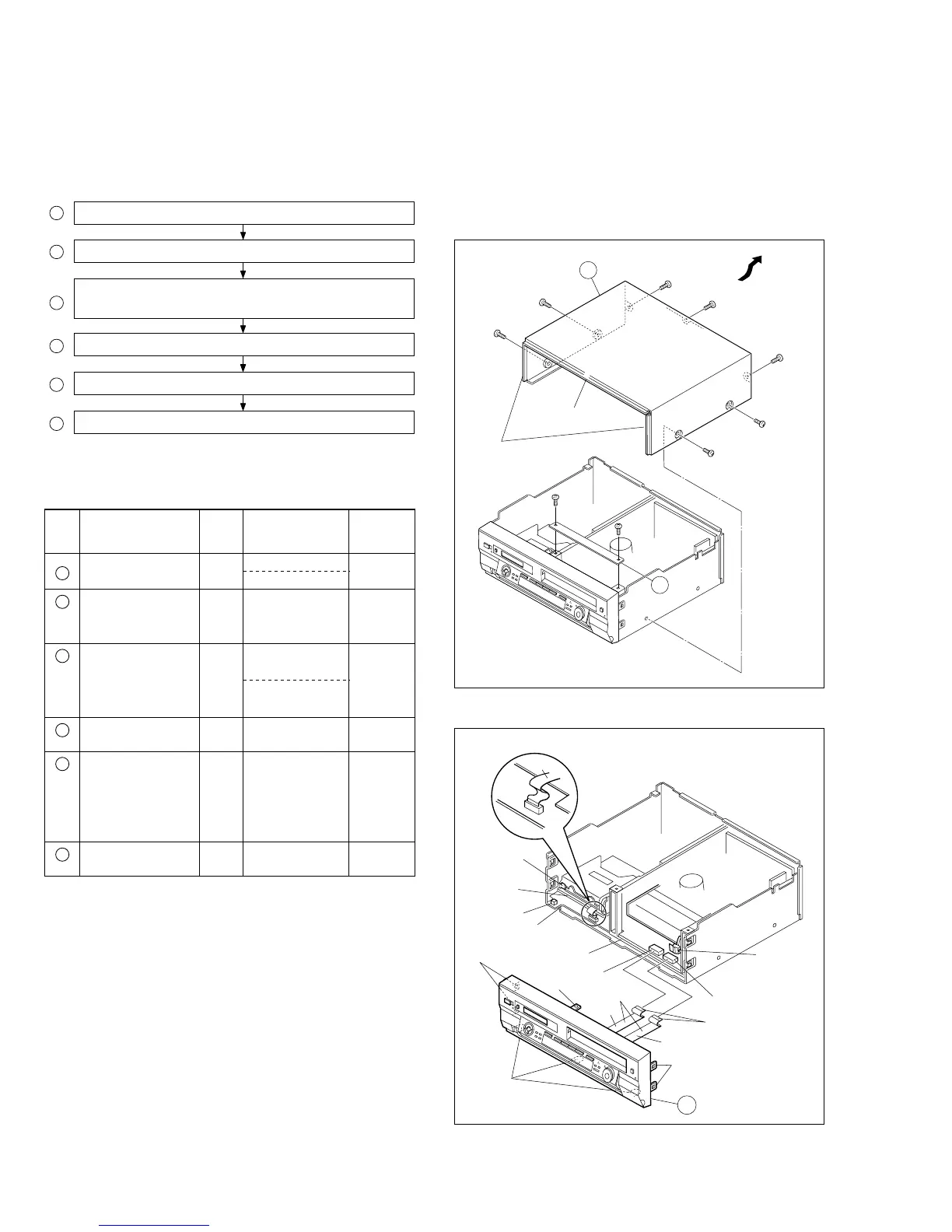
1 Top cover, Bracket
2 Front panel assembly
Display board assembly, Display/SW board assembly,
3
SW board assembly, LED1, 2 board assembly
4 SW REG board assembly
5 Regulator board assembly
6 Rear cover
<Note 1>
When attaching the FPC, be sure to connect it in the cor-
rect orientation.
<Note 2>
When attaching the front panel assy, make sure that the
door openers of both decks (DV, VHS) are in the down
position.
<Note 3>
When attaching the front panel assy, be careful not to dam-
age the DV terminals.
<Note 4>
When attaching the FPC take care that it is not caught.
Pass the DV-side FPC between the base (2) and DV Main
board assy.
Pass the two VHS-side FPCs below the base (1).
1.5.2
Disassembly/assembly method <COM section>
<Note 5>
When removing the SW REG board assembly or Regula-
tor board assembly, unhook the several spacers connect-
ing it with pliers from the top side.
<Note 6>
Perform the work by leaving fan motor attached to the rear
cover except when replacing the fan motor.
When attaching the rear cover, please be careful with the
wiring.
Fig. COM1
Top cover
7
(
S2
)
5
(
S2
)
4
(
S1
)
3
(
S1
)
6
(
S2
)
2
(
S1
)
1
(
S1
)
1
(
L1
)
(
L2
)
1
8
(
S3
)
9
(
S3
)
Bracket
(
L3
)
(
L3
)
<Note 4>
FPC
DV Main board
assembly
WR2
WR1
<Note 4>
<Note 1>
Supporting
tape side
<Note 2>
DV SIDE
<Note 2>
VHS SIDE
Base (2)
Base (1)
<Note 3>
CN7507
CN3011
2
(
L3
)
(
L3
)
Fig. COM2
Step/
Loc No.
Fig. No.
Point NotePart name
Top cover, Bracket COM1
4(S1), 3(S2), 2(L1), (L2)
2(S3)
1
—
—
Front panel
assembly
COM2 8(L3),
CN7507(WR1),
CN3011(WR2)
<Note
1,2,3,4>
<Note 1,
5>
2
SW REG board
assembly
4
COM3 10(S4)
6(S4), Knob(Jog),
Knob(Shuttle),
3
Display board assembly,
LED/SW board assembly,
Eject SW board assembly,
Jack board assembly,
Jog board assembly
COM4 2(S5), 2(L4), (L5)
CN5301(WR3),
<Note 1,
5>
Regulator board
assembly
5
COM5 3(L6),
CN5322(WR4),
CN5321(WR5),
CN5325(WR6),
CN5324(WR7),
CN5323(WR8)
<NOTE 6>Rear cover
6
COM6 4(S2), 6(S6),
Fan motor
 Loading...