2-39
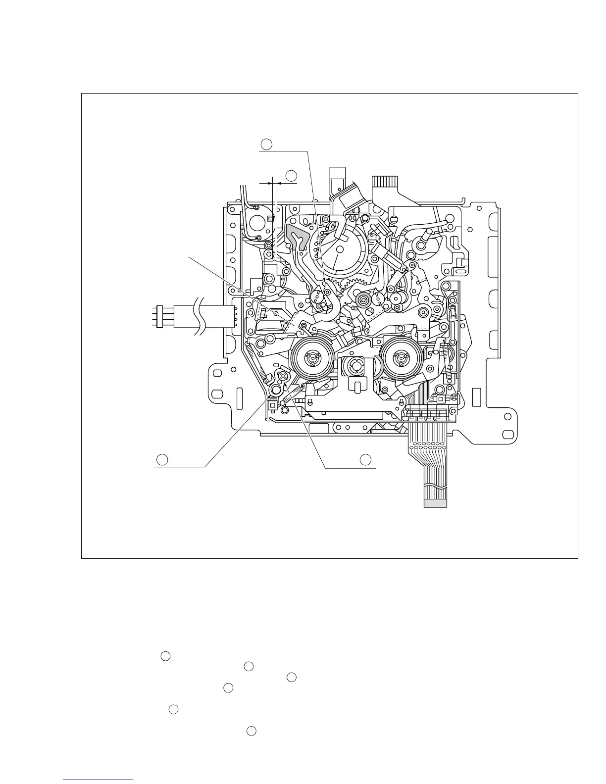
Fig. 2-17-1
2.17 POSITIONING THE TENSION POLE
See Fig. 2-17-1.
D section
Tension Arm Sub
Assembly
Screw A
C
B section
Adjustment Method
Note:
•
Remove the cassette housing assembly in advance.
1. Set the mechanism mode to the PLAY mode. (See pages
2-20 and 21.)
2. Loosen a screw A .
3. Check the location of the tip (section B ) of the tension
arm assembly to make sure that it is within area C .
If it is located outside, turn part D to bring it within the
specified area.
4. Tighten the screw A .
Note :
Tightening torque for the screw
A
: 0.06 Nm (0.6
kgfcm)
 Loading...