133
Transistor Tests
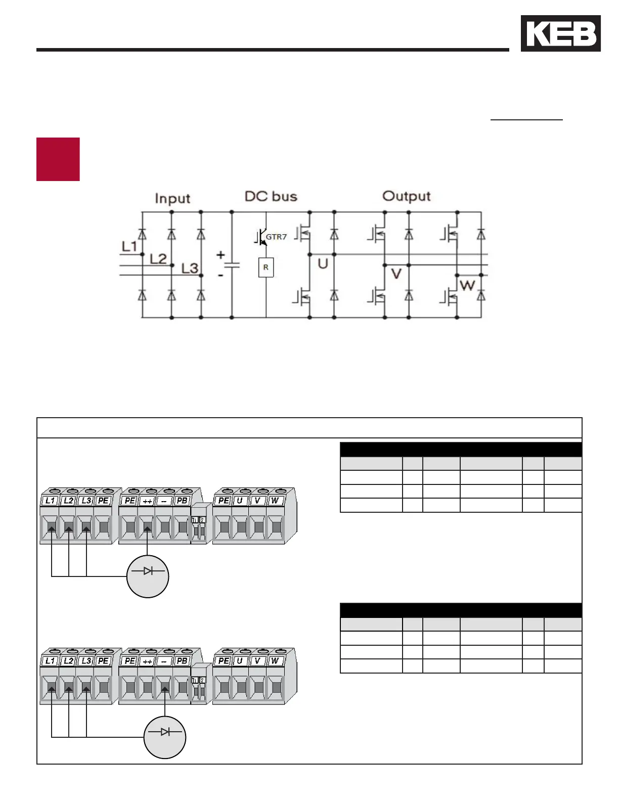
Testing the rectifier, input circuit measurement
The input and output circuits of the inverter can be checked externally with the inverter
power off and the motor leads disconnected by use of a multi-meter set to diode check.
Note: Different drive housings will have different readings. Measured values per
housing are given in tables below.
5.7. Transistor Tests
The inverter power must be de-energized and locked out for these tests! Disconnect
the mains wiring, motor wiring, and braking resistor from the inverter before taking
measurements.
Positive Side
Negative lead of meter to positive DC terminal.
Positive lead of meter to L1/L2/L3 terminals.
E, G, and H Housings
Measurement To Value Measurement To Value
+ Terminal L1 0.4 - 0.5 - Terminal L1 0.4 - 0.5
+ Terminal L2 0.4 - 0.5 - Terminal L2 0.4 - 0.5
+ Terminal L3 0.4 - 0.5 - Terminal L3 0.4 - 0.5
R, U, and W Housings
Measurement To Value Measurement To Value
+ Terminal L1 0.4 - 0.5 - Terminal L1 0.4
+ Terminal L2 Open - Terminal L2 0.4
+ Terminal L3 Open - Terminal L3 0.4
Negative Side
Positive lead of meter to negative DC terminal.
Negative lead of meter to L1/L2/L3 terminals.
Multimeter
Multimeter
+
+
+
-
+- - -
 Loading...


