36
Control Connections
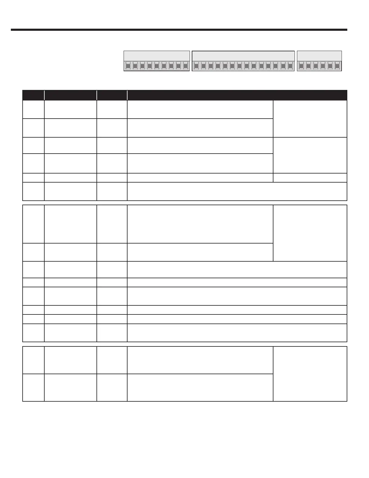
2. Control Connections
2.1. Control Circuit
X2A
Terminal tightening torque = 0.5 Nm
2.1.1. Terminal Strip
Connections F5-A
PIN Function Name Description
1 Analog Input 1 + AN1+
Pattern speed input
Resolution: 12 bit
2 Analog Input 1 - AN1-
3 Analog Input 2 + AN2+
Pre-torque input
Scan time: 1 ms
4 Analog Input 2 - AN2-
5 Analog Output 1 ANOUT1 Analog output of the motor speed closed loop, calcu-
lated open loop
Voltage range: 0...±10V
6 Analog Output 2 ANOUT2 Analog output of the motor torque
0...10VDC (0...2xT
Rated (motor)
)
Ri = 100 kOhm,
resolution: 12 bit
7 +10V Output CRF Analog supply voltage for speed ref. +10VDC +5%, max. 4mA
8 Analog Common COM Common for analog in- and outputs
9 Analog Common COM
10 Prog. Input LI04 I1 When I1...I6, I8 are assigned as speed selection,
I1>I2>...I8
Inputs not used for speed selection can be assigned
special functions.
Ri = 2.1 kOhm,
scan time: 1msec,
LI02 digital lter reduces
false trigger due to relay
chatter, lter time: 10-
100msec (adjustable)
11 Prog. Input LI05 I2
12 Prog. Input LI06 I3
13 Prog. Input LI07 I4
14 Prog. Input LI08 I5 When I1...I8 are assigned as direction inputs, both
directions cannot be signaled together
15 Prog. Input LI09 I6
16 Drive Enable I7 Enable/Disable; response time < 1 msec;
Enable instantly turns off motor current
17 Prog. Input LI11 I8 Same as I1...I6
18 Digital Out 1 O1 Programmable output LO05 - Default = At Speed
19 Digital Out 2 O2 Programmable output LO10 - Default = Deceleration Active
20 24V-Output V
out
Approx. 24V output (max.100 mA load)
21 20...30V-Input V
in
Voltage input when an external 24VDC supply is used
22 Digital Common 0V Common for digital in-/outputs
23 Digital Common 0V Common for digital in-/outputs
24 Relay 1 NO
Programmable output LO15 - Default “Off”
max. 30VDC, 1A
25 NC
26 COM
27 Relay 2 NO
Programmable output LO20 - Default - “Brake Con-
trol”
28 NC
29 COM
 Loading...


