33
Ferrite Ring Installation
All PWM type frequency inverters generate high frequencies as a result of
fast switching of the IGBT output transistors. As these high frequencies trav-
el along the motor wires they can easily be coupled to other wires in proxim-
ity to the motor leads. This is especially true for low voltage encoders. The
included ferrite rings can be used to limit the high frequency noise which is
transmitted on the motor wires by inserting a small amount of inductance
on each motor lead. These rings can also be useful when shielded cables
are used, since they will limit the available high frequencies even before the
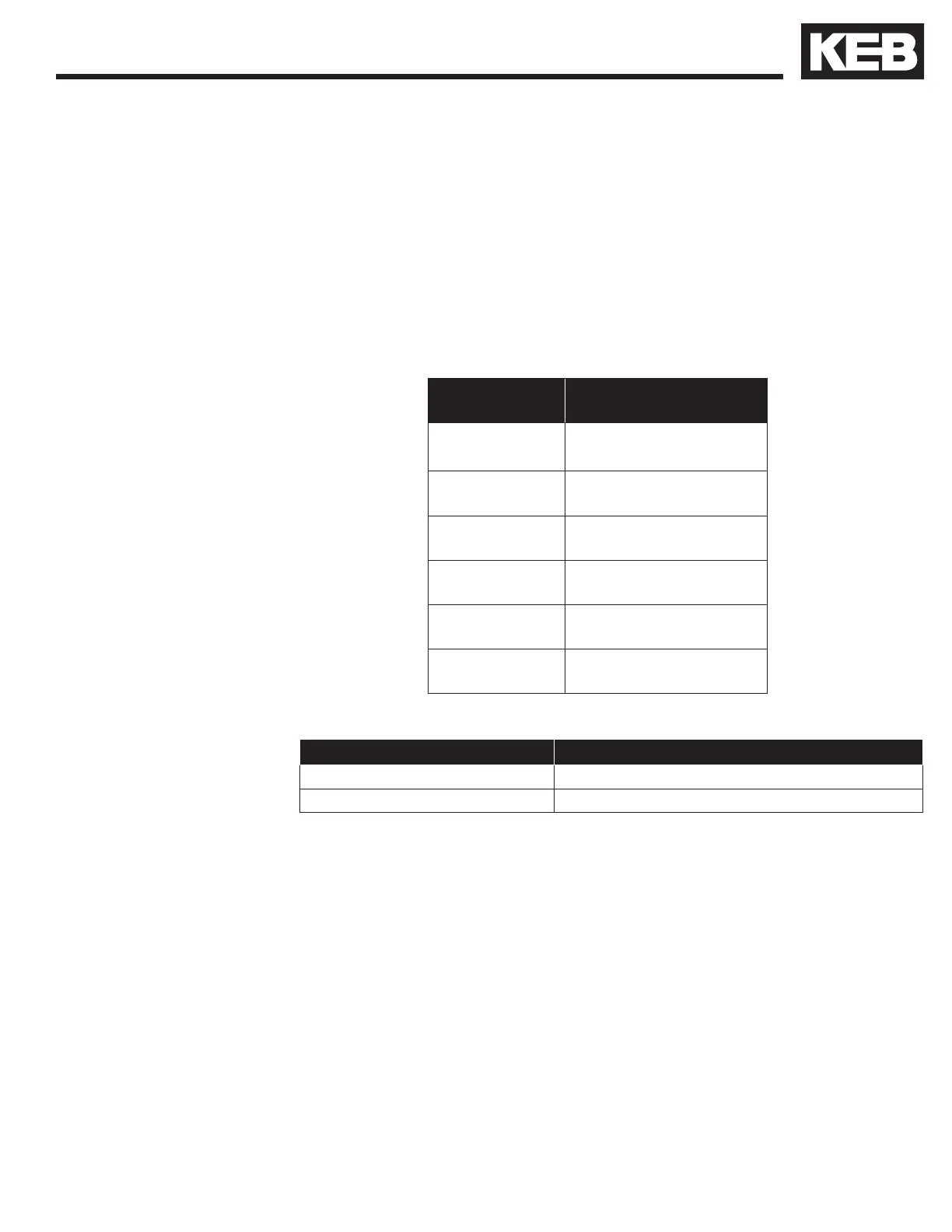
shield on the cable. Refer to the following table for quantity and part num-
bers.
Housing Size Quantity All Phases
(Part Number)
‘E’ 1
(00.90.390-K000)
‘G’ 1
(00.90.390-K000)
‘H’ 1
(00.90.390-K000)
‘R’ 1
(00.90.395-K001)
‘U’ 2
(00.90.395-K001)
‘W’ 2
(00.90.395-K001)
1.9.
1.10.
Part Number Overall Dimensions in mm (inches)
00.90.390-K000 56 x 32 x 18 (2.2 x 1.3 x 0.7)
00.90.395-K001 63 x 38 x 25 (2.5 x 1.5 x 1.0)
1.8.1. Ferrite Ring
Installation
 Loading...


