32
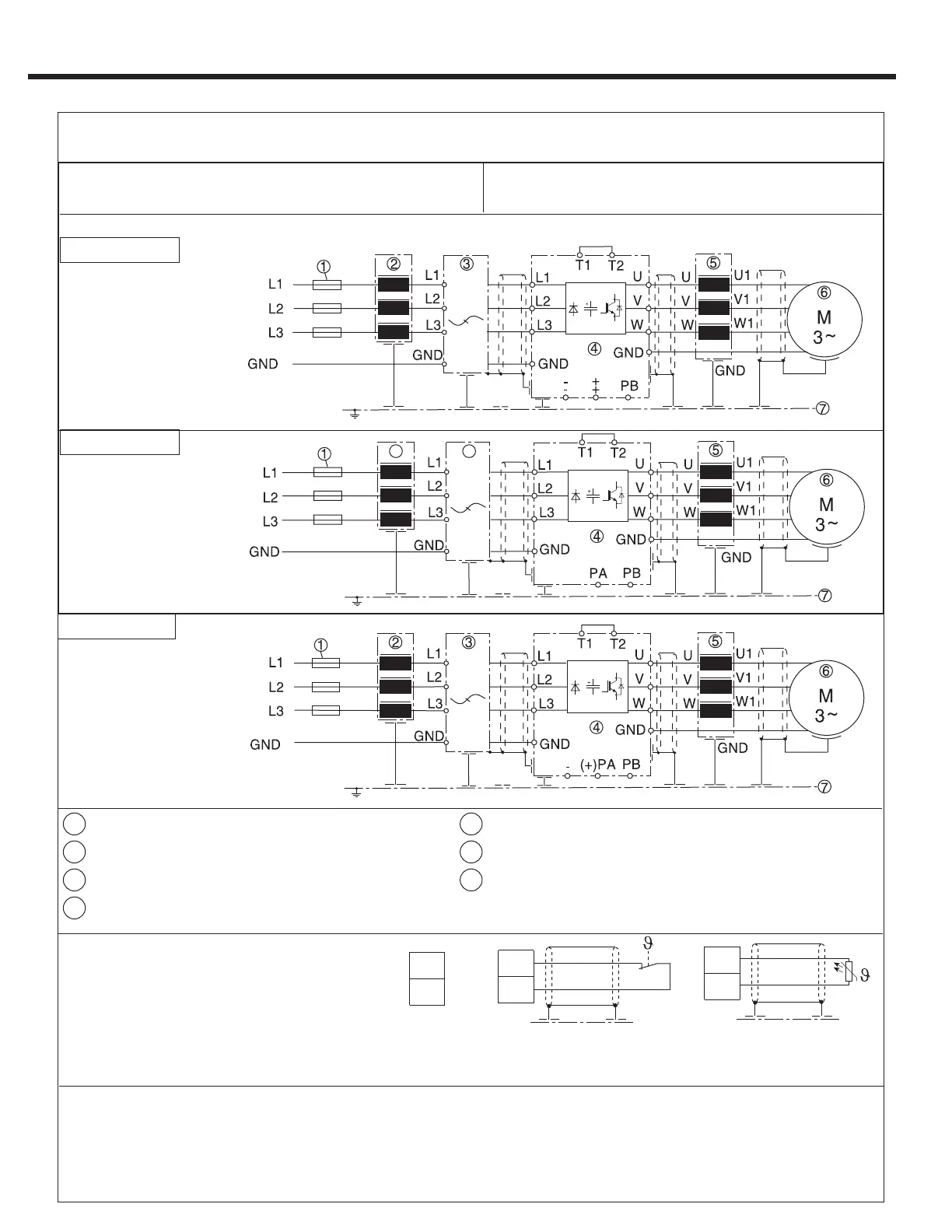
Power Circuit Terminal Summary
Connection of braking resistor
(Braking circuit installed as standard in
housing sizes E,G,H, R and U.)
External motor temperature sensor
(for all units)
Thermal switch
(NC-contact)
No jumper required, when
a sensor is not connected
Temperature sensor (PTC )
1650Ω...4kΩ tripping resistance
750Ω...1650Ω reset resistance
Don't install sensor wires with control wires!
Must use double shield when running these
wires with motor wires!
It is necessary to activate this function via
software parameter! See LX10
Wiring diagram 3
1
Supply fuse
5
Motor Choke or Output Filter
2
Line Choke
6
Motor
3
Interference Suppression Filter
7
Sub-Panel in Control Cabinet
4
COMBIVERT F5
*Main disconnect /
feeder circuit not shown
If the supply voltage is connected to the motor
terminals, the unit will be destroyed!
Pay attention to the supply voltage 230/480V
and the correct polarity of the motor!
See technical data in Sections 1.4-1.5 to match the wiring diagram to inverter size and housing type.
Wiring diagram 1
Wiring diagram 2
1.8. Connection of the power circuit
2
3
*Main disconnect /
feeder circuit not shown
*Main disconnect /
feeder circuit not shown
IMPORTANT: See Section 2.2.4 for Fusing Specications
Refer to section 1.2.15 for wiring diagrams
 Loading...


