46
2.2.3. Incremental
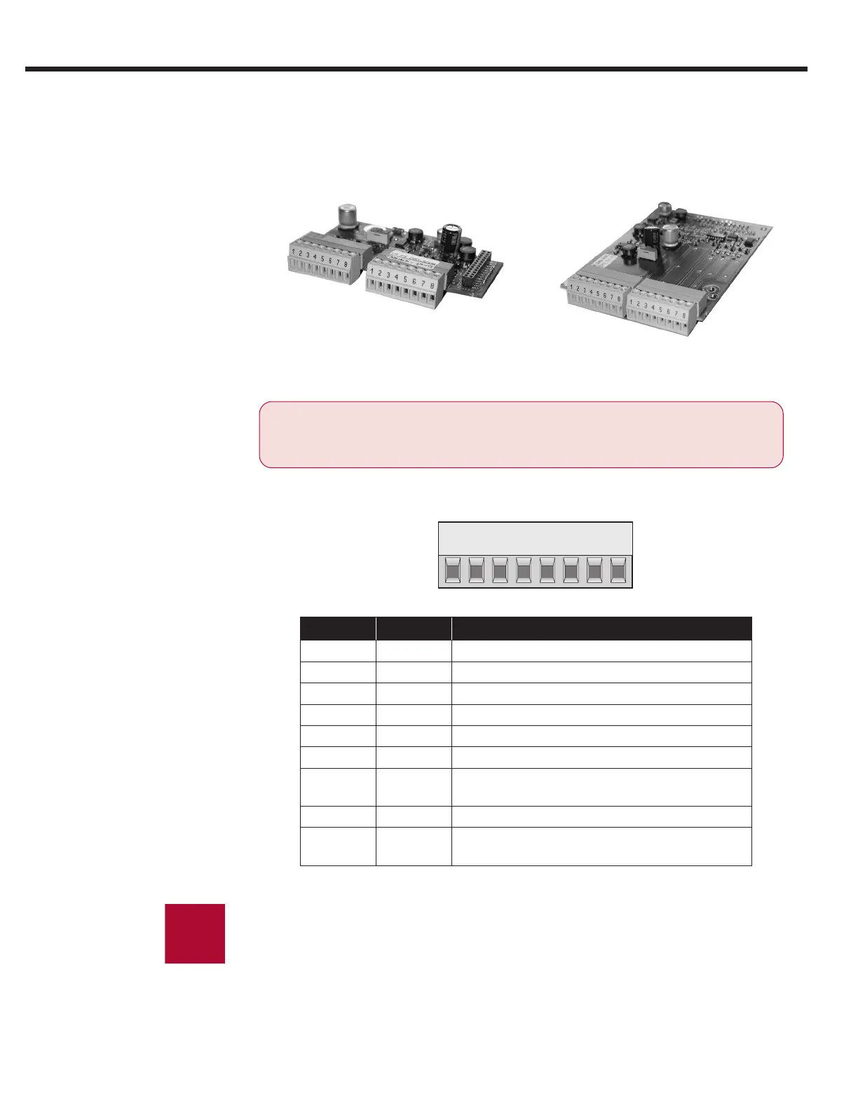
TTL Encoder
Interface X3A
Screw Terminals
Connect the incremental encoder mounted on the motor to the 8 posi-
tion terminal connector at X3A. This connection provides speed feed-
back and is imperative to the proper operation of the F5.
ONLY when the inverter is switched off and the volt-
age supply is disconnected may the feedback con-
nectors be removed or connected!
X3A
Channel 1
X3B
Channel 2
X3A
Channel 1
X3B
Channel 2
Plug in screw
terminal X3A
Pin No. Signal Description
1 A+ TTL incremental encoder track A
2 A- Differential signal to A+
3 B+ TTL incremental encoder track B
4 B- Differential signal to B+
5* N+ TTL Zero track
6* N- Differential signal to N+
7** 15/24 V
Voltage output 15/20...30 V, power supply for
the encoder, switchable with dip switch S100
8 COM 0V reference for voltage supply
- GND
Connect the outer cable shield to an earth
ground connection on the elevator drive
*If the encoder has no zero channel, connect N+ (X3A.5) to 5V (X3B.7)
and N- (X3A.6) to 0V common (X3A.8 or X3B.8) to avoid ‘Error Encoder1’
faults.
**For 5V supply TTL encoders, a 5V supply is available on the second
interface channel, X3B.7.
 Loading...


