45
Control Circuit - STO
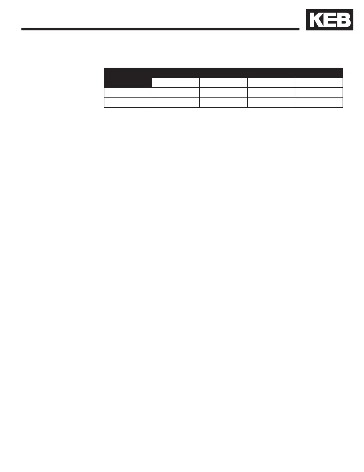
Specication of the STO inputs
STO Inputs
Status 0 Status 1
UL (V) IL (mA) UH (V) IH (mA)
max. 5 25 30 25
min. -3 not dened 15 5
The maximum short-term starting current of the input is limited to 300 mA.
The short-circuit proof, digital output is specied in accordance with IEC 61131-
2. The output current is 100 mA at 24VDC.
The output is 24VDC if modulation is possible. Inputs STO1, STO2 and ST
must be set for it.
The STO circuitry requires a control sequence specic to the F5-K card. The
X2A.16 hardware enable and all X2B STO inputs are ANDED to activate
the I7 drive enable. In addition if either the X2A.16 hardware enable or any
X2B STO inputs are deactivated the I7 drive enable will also deactivate
preventing drive modulation. Verication of the hardware enable and STO
inputs can be seen in DG.01. The X2A.16 hardware enable will be displayed
as ST-EXT (8192) and the STO input will be displayed as STO (4096) in the
DG.01 input status. Once ST-EXT and STO are activated the I7 (1) input will
be activated.
2.2.9. STO Inputs
(F5-K)
2.2.10. STO Output
(F5-K)
2.2.11. STO Input
Control Sequence
(F5-K)
 Loading...


