23
Model Number Information
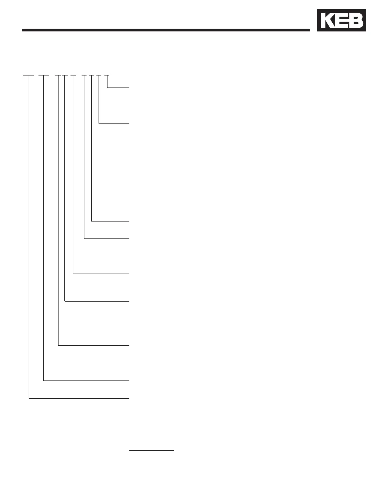
1.3. Model Number Information
Part Number
17.F5.A1G-RLBB
Unit Ident. B= LCD Oper. with Serial/CAN
D = LCD Oper. with Serial/CAN + boosted peak output
Feedback Card 0 = None installed at the factory
B = Incremental TTL (terminal) .... TTL output
D = Incremental TTL (SubD) ....... TTL output
F = Hiperface ..............................TTL output
M = Sin/Cos ................................TTL output
P = EnDat ...................................TTL output
V = SSi .......................................TTL output
9 = UVW .....................................TTL output
*Additional interfaces types and channel
configurations available
Application L = KEB Elevator Drive
Voltage Ident. R = 480V, 3-Phase
P = 230V, 3-Phase
Housing Type E, G, H, R, U, W
Accessories 1 = Braking transistor
1
standard
3 = Braking transistor and EMI filter
Control Stage A = Standard Board - all motor types
K = Safety Board - all motor types, STO
Unit Type F5
Unit Size 10 = 3 hp 17 = 25 hp 23 = 100 hp
12 = 5 hp 18 = 30 hp 24 = 125 hp
13 = 7.5 hp 19 = 40 hp 26 = 175 hp
14 = 10 hp 20 = 50 hp 28 = 250 hp
15 = 15 hp 21 = 60 hp
16 = 20 hp 22 = 75 hp
1 For F5 housing sizes G, H, R, U and W the braking transistor
monitor circuit will be included on all units delivered after May 2021.
 Loading...


