40
MECHANICAL INSTALLATION
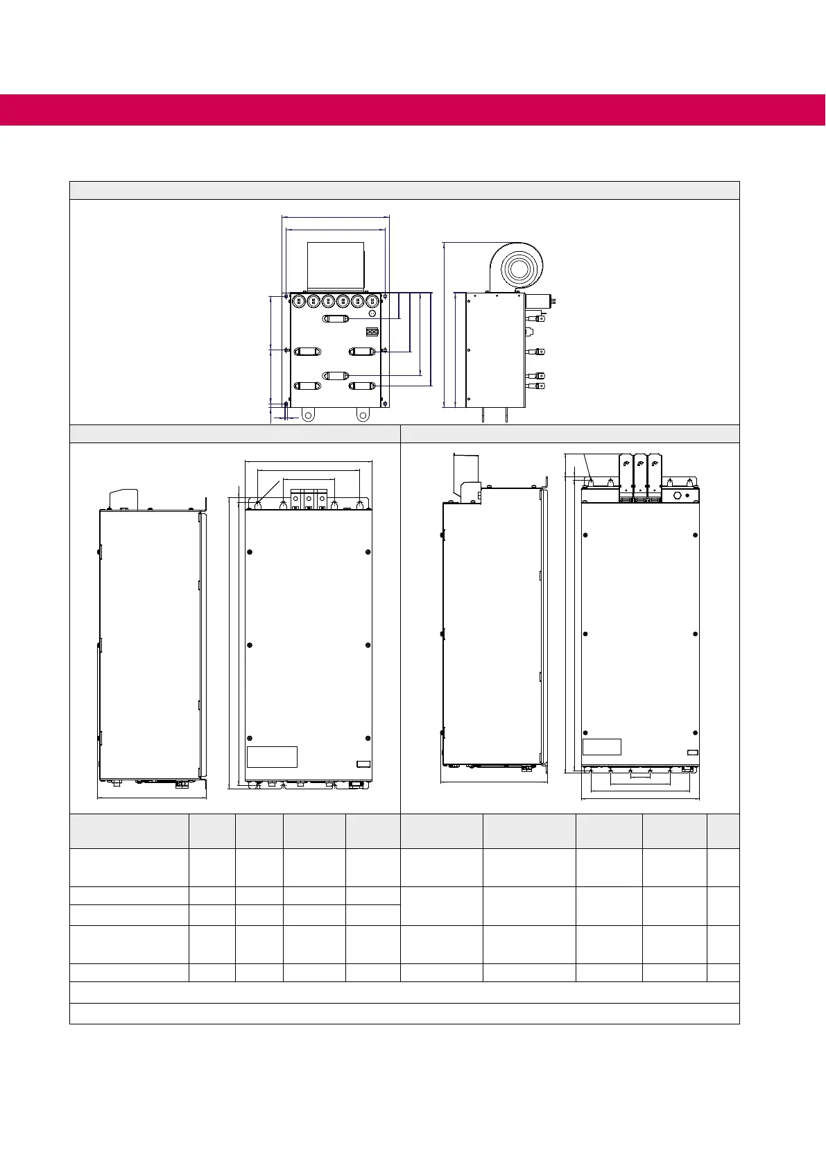
3.4.7 AIC lter 3x400 V AC for switching frequency 4…16 kHz
Figure 1
15 220 220
405
440
9
106,5
241,5
340
381
675
470
Figure 2 Figure 3
570
555 9
4x
Ø 6,5
100
200
249
270,5
735 9
750
50
150
250
299
58
6x
Ø 6,5
Material number IN in A
fS_min
in kHz
S in kVA PD in W Connection
Tightening
torque
PE-
terminal
Weight
in kg
Fig-
ure
24H6J4F-1000 108 8 75 590
16…50mm²
AWG6-0
4 Nm M8 40 2
24H6J4G-1000 180 8 125 1100 M10
Stud
25 Nm
220lbinch
M10 68 3
26H6J4G-1000
1)
150 8 104 695
26H6J4G-A000 150 8 104 695
M10
Stud
25 Nm
220lbinch
M10 60 3
26Z1K04-1000
2)
250 4 173 1300 M8 12 Nm M8 91.6 1
I
N: Rated current; fSN: Switching frequency; S: Apparent power; PD: Power dissipation
Figure 9: AIC lter 3x400 V AC for switching frequency 4…16 kHz
1)
26H6J4G-1000 with sinus EMC level.
2)
For operation without sinus EMC level, the connections U1.2-U1.3, V1.2-V1.3 and W1.2-W1.3
must be bridged. The EMC lter 26E4T60-1001 must be used for rated operation.
 Loading...


