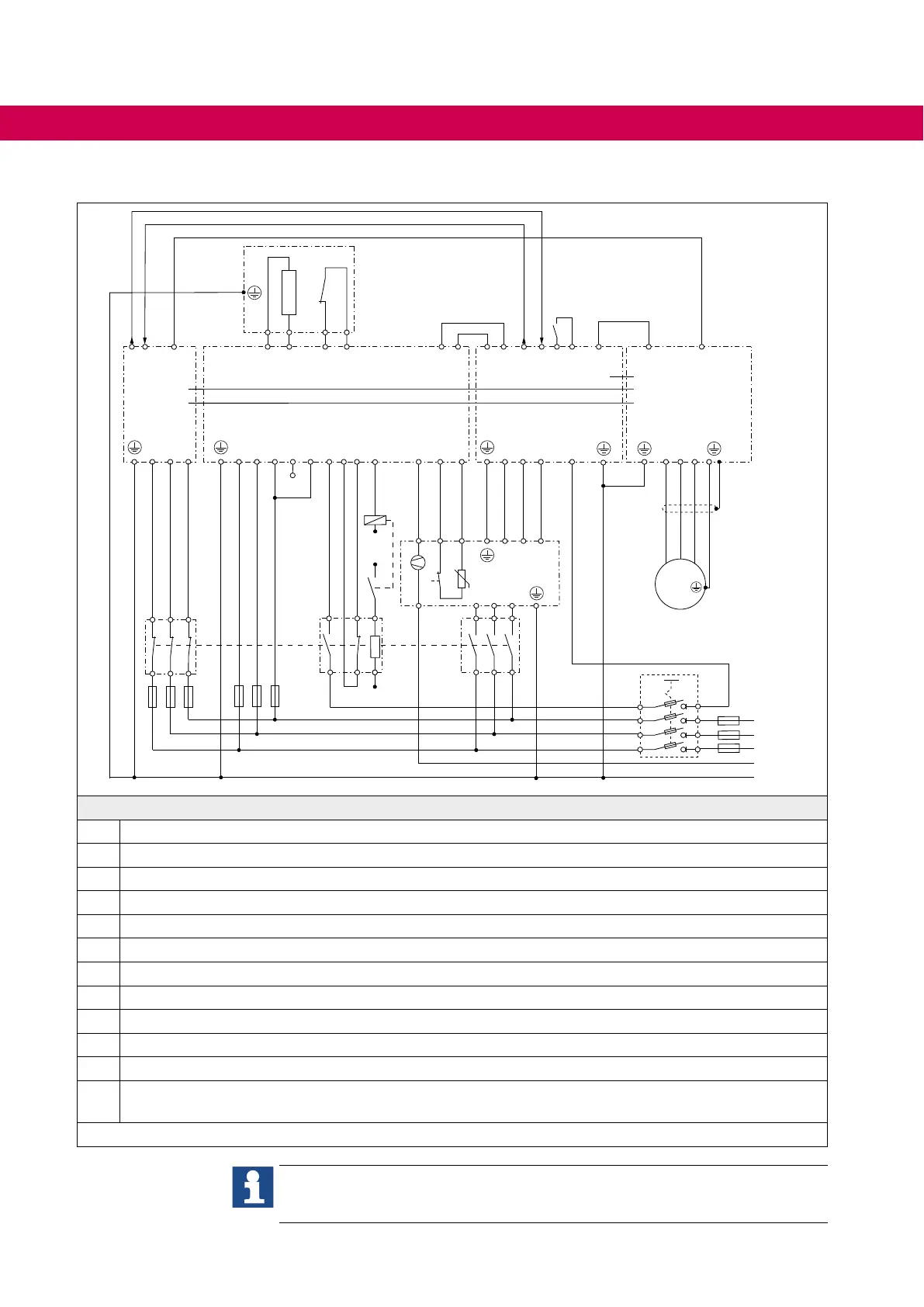
4.3.4 Connection of lter, AIC, charging module and control at DC bus
N
L3
L2
L1
L3
L2
L1
C-in
C-out
F-in
F-out
F-T1
F-T2
C2
C1
①
ϑ
PB
PA
R-T1
R-T2
④
⑦ ⑧⑩
⑫
U V W
24Vdc
DC-Bus
⑨
M
ErrorError
U V W
L3 L2 L1
ϑ
+
KTY84
⑤
EtherCAT
⑪
U V W
②
24Vdc
0Vdc
A
A1
A2
PE
EtherCAT
EtherCAT
DI1
EtherCAT
DO1
DO1
DI3
DO2
DI2
24V
ST
DI1
DO2
③
24Vdc
DC-Bus
L3
L2
L1
⑥b ⑥a
⑥c
Legend
1 Main fuses
2 Main switch S1
3 Pre-charging fuses
4 Braking resistor with temperature switch
5 AIClterwithfanandtemperaturemonitoring/switch-o
6 Mains contactor K1 with protective circuit
7 Charging module
8 AIC module
9 Axis module
10 24V power supply module with superior control
11 Motor
12
Decoupling relay with protective circuit (the decoupling relay is not required, if ensured that the load capac-
itiy of the relais contact is not exceeding).
Figure 30: Connection of lter, AIC and charging module
TheconnectionlinesbetweenAICandlterarepartlyunshieldedandmustbe
laid at a distance of 15 cm from other cables. => „EMC-compatible installation“.
56
CONNECTION OF THE POWER UNIT
 Loading...


