4.4.5 Assembly of the wires to PUSH IN terminals
NOTICE
Malfunctions caused by loose cable connections!
► Observe metal sleeve length and stripping length
Cross-section Wire-end ferrule
Metal sleeve
length
Stripping
length
0.50mm
2
with plastic collars
(DIN 46228-4)
10mm 12 mm
0.75mm
2
12 mm 14 mm
1.00mm
2
12 mm 15 mm
1.50mm
2
without plastic collars
(DIN 46228-1)
10mm 10mm
0.2…1.5mm
2
single-wireorne-wire
without wire-end
ferrule
– 10…15mm
Table 18: Wire-end ferrules and stripping length
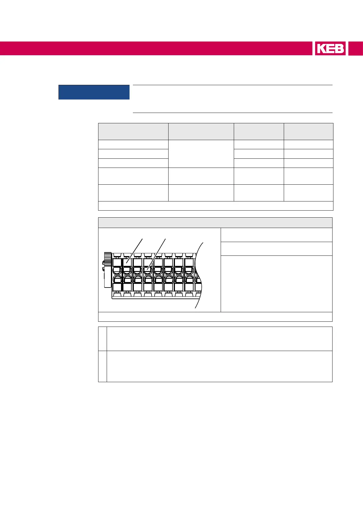
Front view
a) Pusher
b) Wire hole
Figure 35: Assembly of the control cable
•
Press pusher by hand. Insert connecting wires into the respective hole, that no
singlewirescanbeseenfromtheoutsideorbendoutward.Arstresistancemust
be overcome when inserting. Release the pusher.
•
Checkthattheconnectingwireisxedandcannotbepulled-out.Itisimportantto
ensure that the connecting wire and not the insulation is clamped. The connecting
wire can also be inserted without pressing the pusher in case of cross-sections
upto1.00mm².
61
CONNECTION OF THE CONTROL
 Loading...


