EasyManuals Logo
Home>KEB>Control Unit>COMBIVERT H6 Series

KEB COMBIVERT H6 Series User Manual

KEB COMBIVERT H6 Series
82 pages
To Next Page IconTo Next Page
To Previous Page IconTo Previous Page
Page #57 background imageLoading...
Page #57 background image
4.3.5 Temperature monitoring of the braking resistor
4.3.5.1 Terminals R-T1, R-T2
NOTICE
Connect the safe separated temperature switch at the input of the charg-
ing unit.
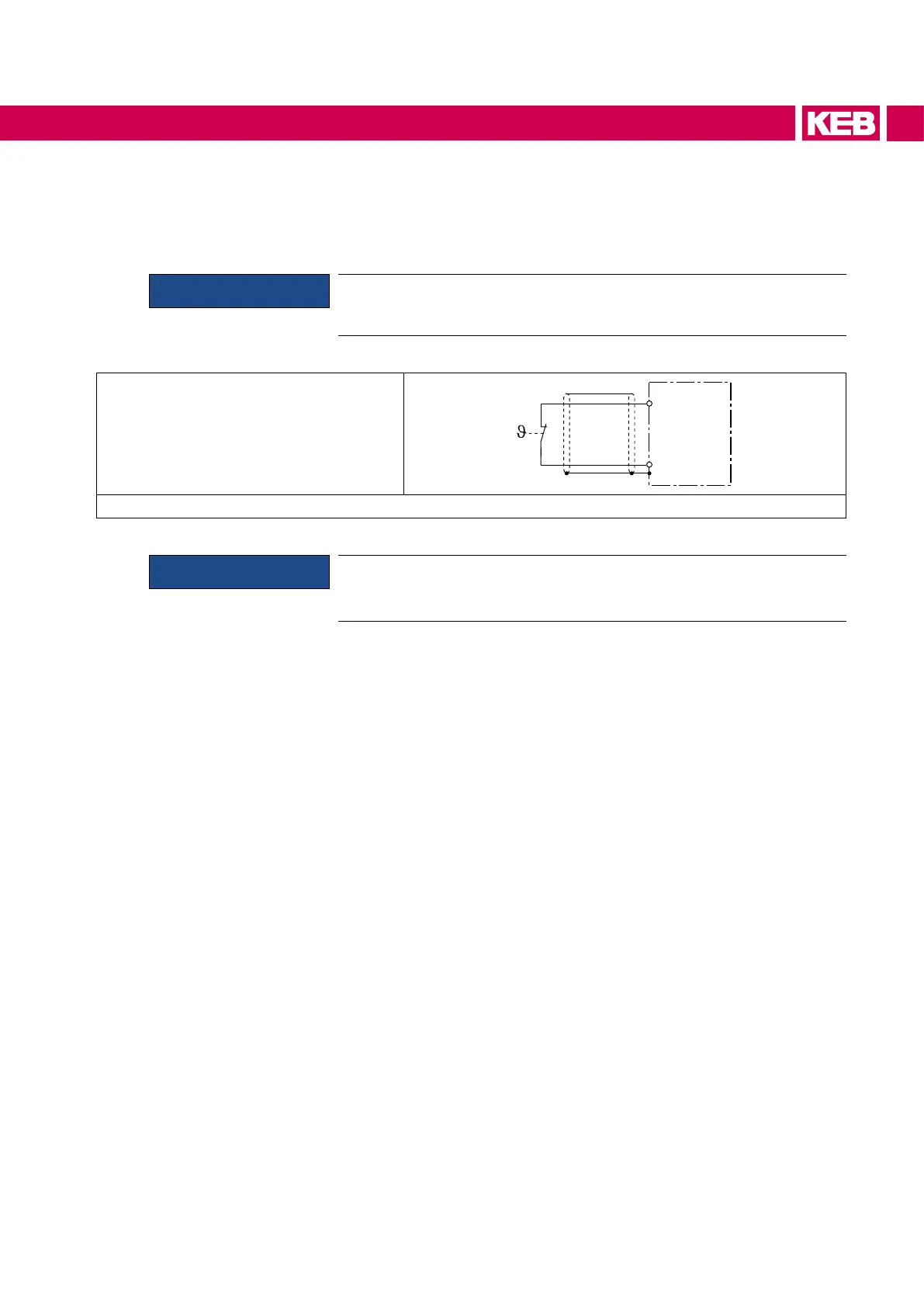
Thermal contact (NC contact)
minimum switching current: 2 mA
R-T1
R-T2
Figure 31: Wiring example temperature monitoring
NOTICE
If no braking resistor is required, a bridge must be installed between
R-T1 and R-T2 to evaluate the input, otherwise there is no precharging
and modulation.
57
CONNECTION OF THE POWER UNIT

Table of Contents

Questions and Answers:

Question and Answer IconNeed help?

Do you have a question about the KEB COMBIVERT H6 Series and is the answer not in the manual?

KEB COMBIVERT H6 Series Specifications

General IconGeneral
BrandKEB
ModelCOMBIVERT H6 Series
CategoryControl Unit
LanguageEnglish

Related product manuals