General designs
© KEB, 2015-07 COMBIVERT R6-N Page6.1 - 3
6
6. Project Design
The following chapter shall assist you in the planning stage of applications.
6.1 General designs
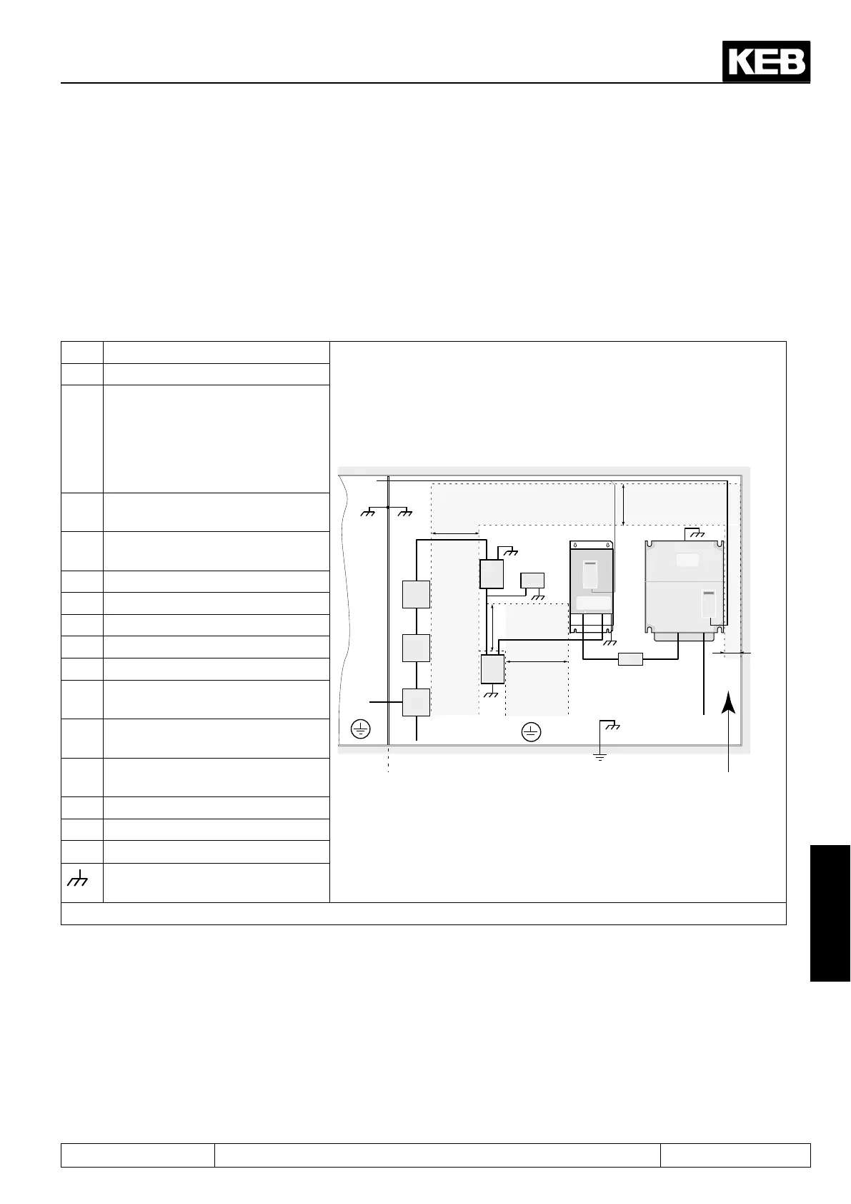
6.1.1 Control cabinet design
1 Main fuse
150 mm
30 mm
150 mm
1
2
8
10b
10c
10a
11
11a
12
4
3
5
150 mm
150 mm
6
7
9a 9b
2 Main contactor
3 EMCside-mountedlter(≤size
19)
(>=size 25 R-S or R6-N)
EMC-sub-mountedlter
(<=size 19 R6-S)
4 Optionally, external power limit /
synchronization R6-S
5 Commutation reactor / harmonic
lter
6 COMBIVERT R6
7 if necessary external DC fuses
8 Frequency inverter
9a DC cables with ferrite DC-
9b Motor cable with ferrite
10 A Protective Earth (PE) on the
mounting plate power circuit
10b Protective Earth (PE) on the
mounting plate control circuit
10c Equipotential bonding with the
housing earth
11 Mains connection power circuit
11 A Mains connection control circuit
12 Control lines
Large area contact at the mount-
ing plate
EMC-compatible control cabinet installation
Control circuit Power circuit Direction of
the
coolingns
 Loading...
