Digital in- and outputs
© KEB, 2015-07 COMBIVERT R6-N Page3.4 - 15
3
10
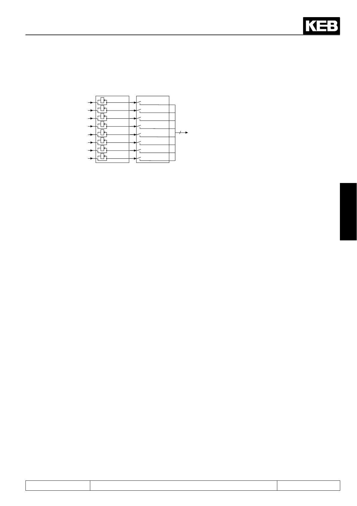
Fig. 3.4.16 Inverting and selection of switching conditions
8
do.24
1
1
1
1
do.8...do.15
do.0
do.1
do.2
do.3
do.4
do.5
do.6
do.7
1
2
4
8
16
32
64
128
do.16...do.23
1
2
4
8
16
32
64
128
1
1
1
1
Eachofthe8switchingconditions(do.00...do.07)canbeinvertedseparatelyforeachagwithparameters
do.08...do.15 . Through this function it is possible to set any chosen switching condition as non-condition. The
parameter is bit-coded. The value for the switching condition to be inverted must be entered in do.08...do.15
according to picture 3.4.15. If several conditions shall be inverted, the sum is to be formed.
3.4.17Selectionofswitchingconditionsforags0...7(do.16...do.23)
Theparametersdo.16...do.23servefortheselectionofthe8denedswitchingconditions.Theselectionis
doneforeachagseparately,whereonecanchoosebetweennooneanduptoall8switchingconditions.The
weighting of the selected switching conditions must be entered into do.16...do.23 according to Fig. 3.4.15. If
several conditions shall be selected, the sum must be formed.
3.4.18Linkingtheswitchingconditionsforags(do.24)
After the switching conditons are selected for each output, it can now be determined, how these are linked. As
adefaultallconditionsareOR-operated,i.e.ifoneoftheselectedconditionsismet,theagisset.AnAND
connection is available as further possibility which can be adjusted with do.24. AND connection means that all
selectedconditionsmustbefullledbeforetheagisset.
Parameter do.24 is bit-coded. The table under 3.4.19 shows the assignment.
 Loading...
