Page 3.4 - 8 COMBIVERT R6-N © KEB, 2015-07
Digital in- and outputs
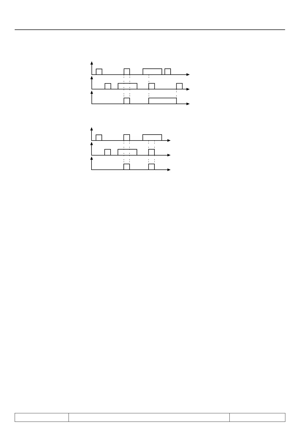
Input signal
t
t
t
strobe signal
Input state
Bild 3.4.8.c Statischer strobe mode 2 (di.07 = 2)
Input signal
t
t
t
strobe signal
Input state
3.4.9 Reset input selection (di.09) and neg slope f. reset inputs (di.10)
Theresetinputisdenedaccordingtable7.3.1withparameterdi.09.Iftheresetinputshallreacttoanegative
slope,oneorseveraloftheresetinputsdenedwithdi.09canbeswitchedtonegativeedgeevaluationwith
di.10.
3.4.10 Assignment of the inputs
There are two fundamentally different procedures for the assignment of inputs.
a.) One or several inputs can be assigned to each function. That means, with the individual functions one
input can be selected which activates this function.
b.) One or several functions can be assigned to each digital input. This means, in parameters di.11...di.22
„Function“ and parameters di.24...di.35 „+ Function“ one or several functions can be assigned to each
single digital input. Several functions can be assigned to the respective inputs with parameters di.11...
di.22 , only one function can be selected with parameters di.24...di.35.
Bothvariantshaveinuenceoneachother;ifaninputisassignedtoafunction,alsoparametersdi.11...di.22
and di.24...di.35 are accordingly adjusted.
Duetothetwovariantstheoperationcombinestwoadvantages:
- bythefunction-relatedprogrammingoftheinputsitcanalsobespeciedwhichinputsshallactivate
the function,
- theinput-relatedrepresentationgivesanoverviewofthecompleteinputfunctionandnallyitcanbe
checked whether unwanted function overlappings have been occured.
Thefollowingtableindicatesaparameterlistwherebydigitalinputscanbeassignedtotheindividualfunctions:
di.09 reset input selection
 Loading...
