Analog output
© KEB, 2015-07 COMBIVERT R6-N Page3.3 - 5
3
10
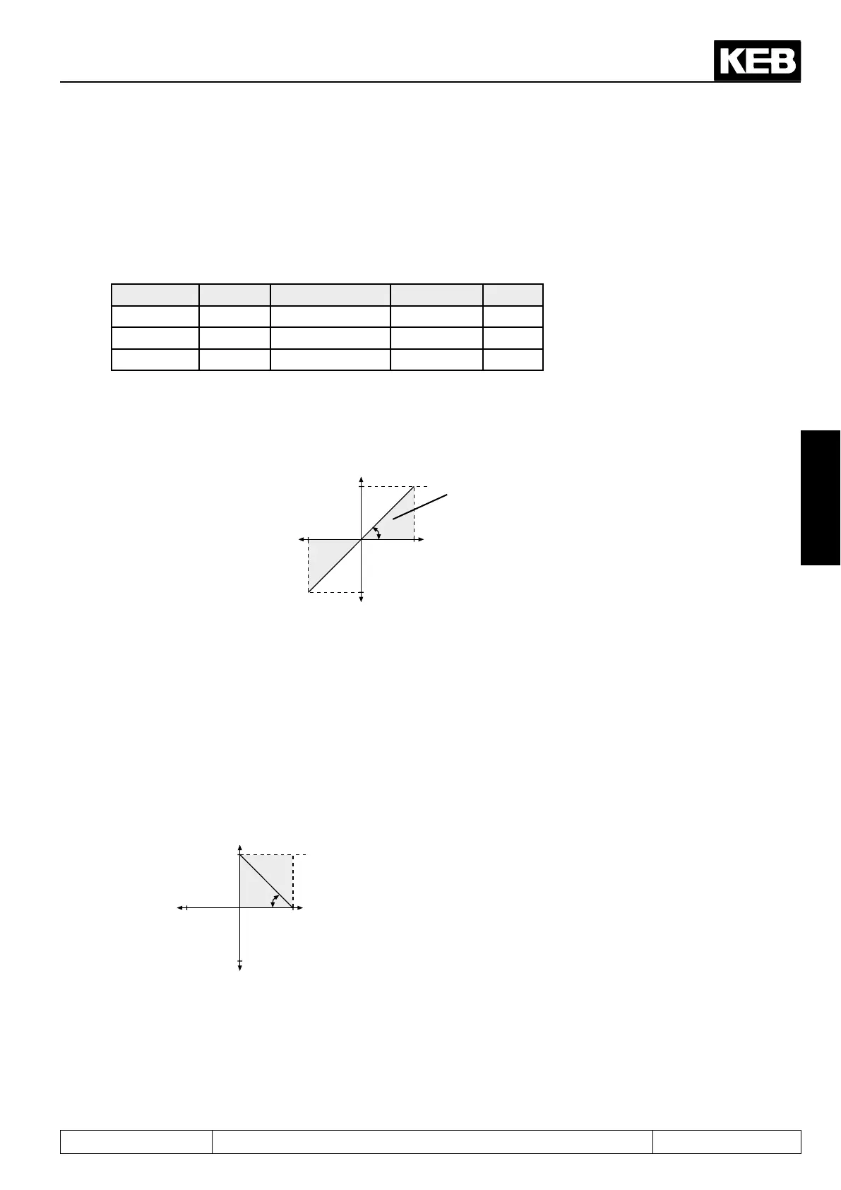
3.3.5 Amplieroftheoutputcharacteristic(An.33...35/An.43...45 / An.49...51)
Asshowninpicture7.2.1,thecharacteristicampliersfollowaftertheselectionoftheoutputsignal. With these
parameters the output signal can be adapted in x and Y direction and in the slope to the requirements. No zero
offsetisadjustedatfactorysetting,theamplicationis1,i.e.,100%oftheoutputsizecorrespondto10Vatthe
analog output (see picture 7.2.2).
Function ANOUT1 Value range Resolution Default
Gain An.33 ±20,00 0,01 1,00
X offset An.34 ±100,0% 0,1% 0,0%
Y offset An.35 ±100,0% 0,1% 0,0%
Picture7.2.5.afactorysetting:nooffset,gain1
Output voltage
10V
100%
-100%
-100%
An.33
An.34
An.35
100%
visible
range
variable to be indicat-
ed
Inverting the analog output
Anexamplefortheuseofthecharacteristicamplierisshowninpicture7.2.5.b
1. set X-Offset (An.34) to 100 (%)
2. set the gain (An.33) to -1.00
Picture 7.2.5.b Invert the analog output
10V
100%-100%
-100%
An.34
An.35
100%
An.33
This adjustments cause an inversion of the analog signal.
0% corresponds 10V at the output
100% corresponds 0 V at the output
Analog output as switch
 Loading...
