Page 3.4 - 12 COMBIVERT R6-N © KEB, 2015-07
Digital in- and outputs
Description
To switch the digital outputs up to 8 conditions can be selected from different conditions. These are entered in
do.00...do.07.Switchingcondition0and1canbelteredbydo.43anddo.44.Parameterru.23shows,ifone
orseveraloftheseconditionsaremet.Foreachagitcannowbeselectedwhichofthe8conditionsshall
apply to it (do.16...do.23). Each condition can still be inverted before selection (do.08...do.15). As a standard
all conditions (if several are selected) are OR-operated. With do.24 this can be changed to AND-operation, i.e.
allconditionsselectedforthisagmustbefullledbeforeitisset.Parameterru.24displaystheagssetin
thislevel.do.33...40formasecondlogiclevel,wherebyaselectionofagsfromlogiclevel1canbemade.
Every individual condition can be inverted with do..25...32. do.41 adjusts the manner of the linkage (AND/OR).
Parameter do.42 is used for inverting one or several outputs. With do.51 the output signals are assigned to
the terminals. ru.80 serves for the display of the status prior to allocation, thereafter ru.25. The internal outputs
OA...OD are directly connected with the internal inputs IA...ID.
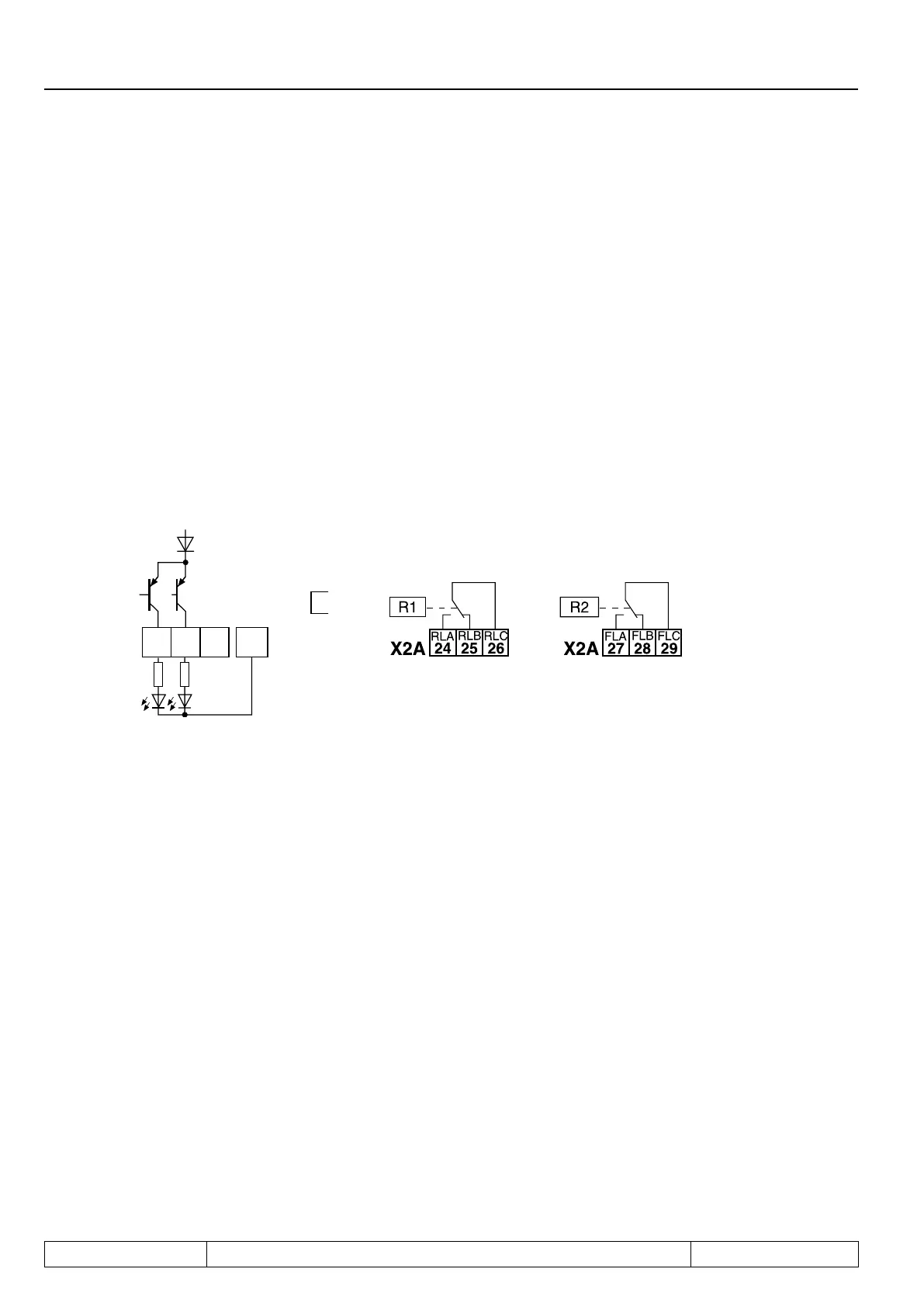
3.4.13 Output signals / hardware
Fig. 7.3.13a Transistor outputs Fig. 7.3.13b Relay outputs
max. 30V / 0,01...2 A max. 30V / 0,01...2 A
The current of X2A.17, 19 is limited to 25mA. A protective wiring shall be provided at inductive load at the relay
outputs or transistor output (free-wheeling diode)!
3.4.14Outputlter(do.43,do.44)
Altercanbesetforswitchingcondition0withdo.43.Withdo.44forswitchingcondition1.Thechangeofa
switchingconditionmustbeappliedfortheltertime,thenitbecomesactiveattheoutputofthelter.Ifthe
changeiscancelledduringtheltertime,theltertimeisresetandrestartedwiththenextchange.Thelter
time can be adjusted in a range of 0 (off)...1000 ms.
3.4.15 Switching conditions (do.00...do.07)
 Loading...
