Digital in- and outputs
© KEB, 2015-07 COMBIVERT R6-N Page3.4 - 5
3
10
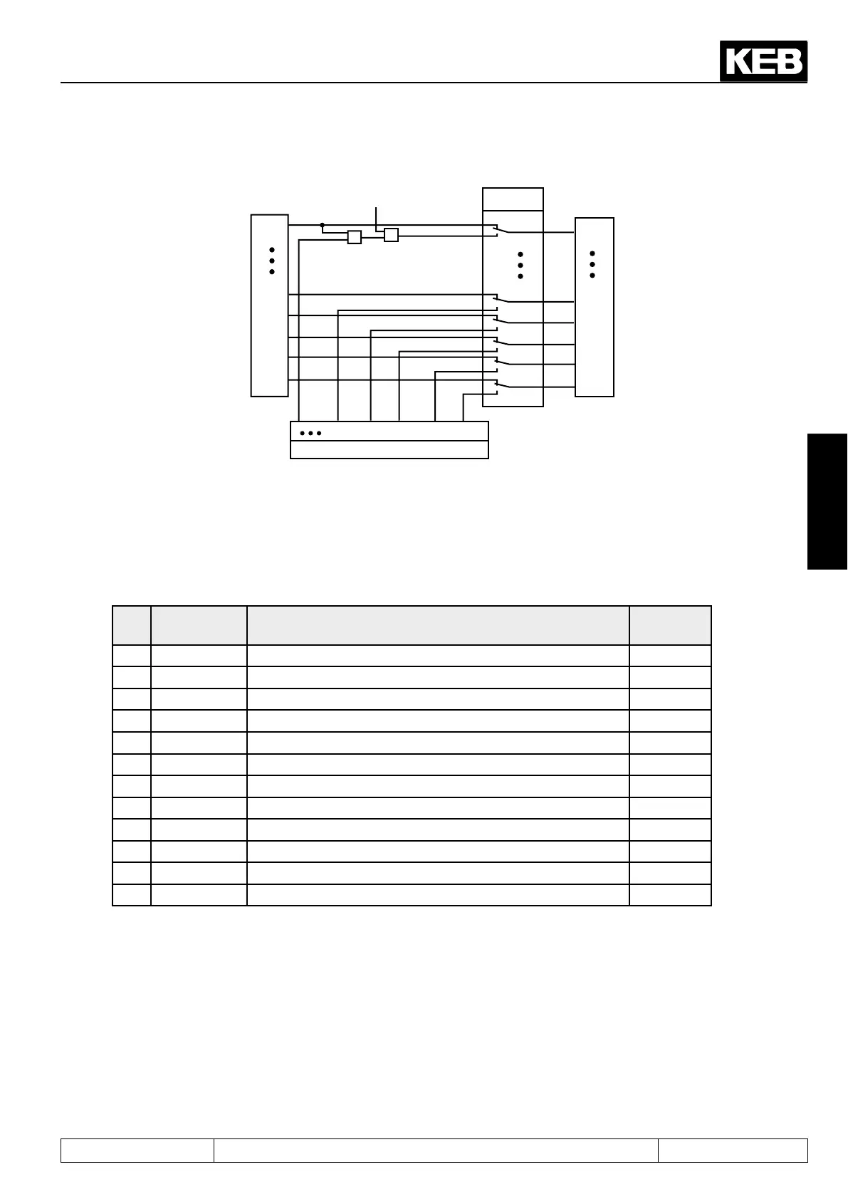
Figure 7.3.3 Digital inputs controlled by software (di.01/di.02)
Inputs
&
&
Sy.50 Bit 0 = 1
di.01
di.02
1 128 256 512 1024 2048
ST
I4
IA
IB
IC
ID
ST
I4
IA
IB
IC
ID
1
128
256
512
1024
2048
As shown in picture 7.3.3 it can be selected with di.01 whether the inputs are switched by terminal strip (default)
or via parameter di.02 . The two parameters are bit-coded, i.e. in accordance with the following table the asso-
ciated value of the input must be entered. With several inputs the sum is to be formed.
(Exception:Controlreleasemustalwaysbebridgedattheterminalstrip).
Table terminal state
Bit Decimal val-
ue
Input Terminal
0 1 ST (external / internal input, see di.22) X2A.12
1 2 RST (internal input, see di.21) no
2 4 F (internal input, see di.19) no
3 8 R (internal input, see di.20) no
4 16 I1 (external / internal input, di.11) X2A.13
5 32 I2 (external / internal input, di.12) X2A.14
6 64 I3 (external / internal input, di.13) X2A.15
7 128 I4 (internal input, di.14) no
8 256 IA (internal input, di.15) no
9 512 IB (internal input, di.16) no
10 1024 IC (internal input, di17) no
11 2048 ID (internal input, di.18) no
Example:ST,FandIBarecontrolled,indicatedvalue=1+4+512=517
3.4.4 Input terminal status (ru.21), internal input status (ru.22)
The input terminal state (ru.21) displays the logical levels at the input terminals. It is irrelevant whether the in-
puts are internally active or not. If a terminal is controlled, then the appropriate decimal value according to the
table below is output. With several active terminals the sum of the decimal values is output.
The internal input state (ru.22) displays the logical state of the digital inputs set internally for processing. If an
input is set, the appropriate decimal value according to the table 7.3.1 is output. If several inputs are set, the
sum of the decimal values is output.
 Loading...
