Page1.3 - 8 COMBIVERT R6-N © KEB, 2015-07
Hardware
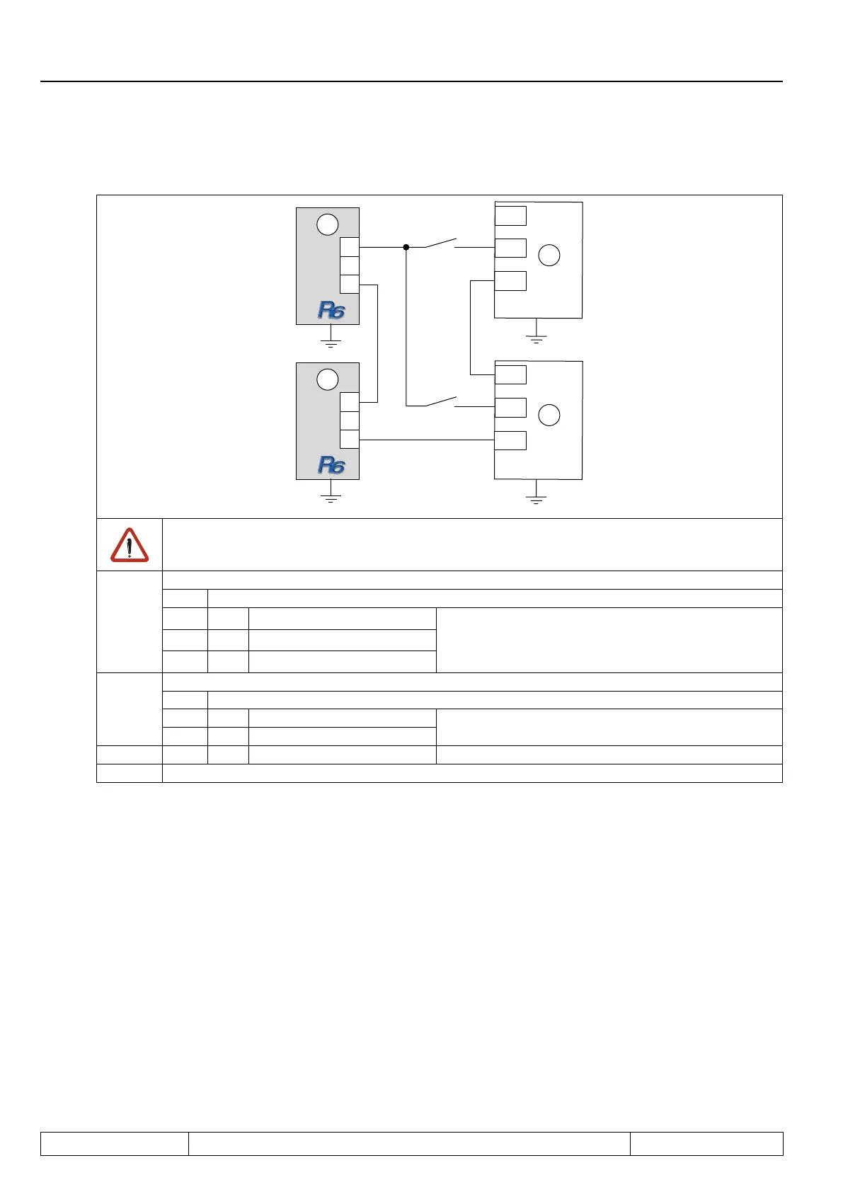
1.3.1.7 Connection of the control release of the connected inverter
STO
0V
25
24
26
S4
G2
X2A
25
24
26
S3
G1
X2A
STO
24V
24V
0V
G3
G4
A load draw in the DC circuit may be done only when the message „ready“ is set. This can be
guaranteed by a series connection of the relay R1 of the R6 units with the control release of the
connected converters.
G1, G2 Regenerative unit COMBIVERT R6
X2A Control terminal strip
24 Relay 1 / NO contact
Ready for operation relay25 Relay 1 / NC contact
26 Relay 1 / switching contact
G3, G4 Frequency inverter
X2A Control terminal strip
STO Control release
General terminal assignment for frequency inverters
24V 24V-output
0V Mass
S3, S4 Control release
 Loading...
