Page 3.4 - 18 COMBIVERT R6-N © KEB, 2015-07
Digital in- and outputs
R2 Relay output 8
OA Internal output 16
OB Internal output 32
OC Internal output 64
OD Internal output 128
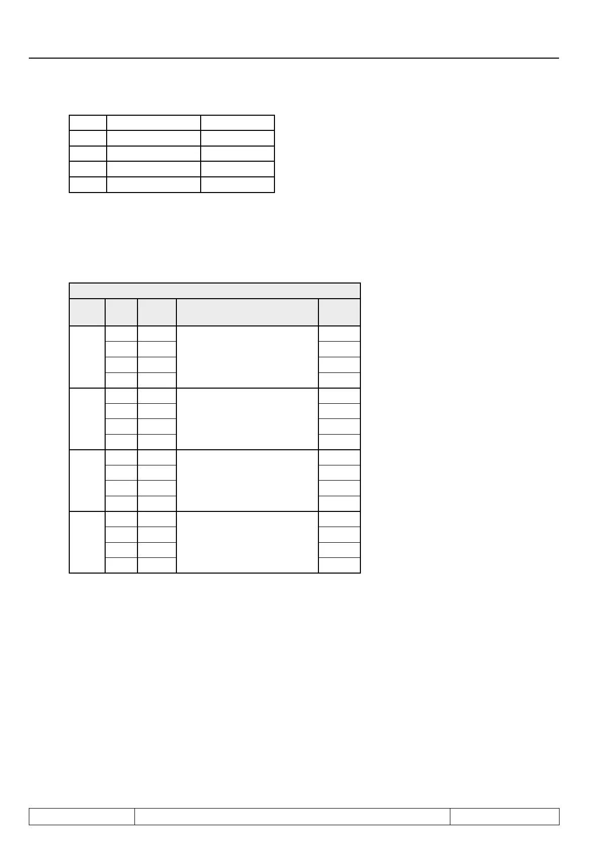
3.4.23 Hardware output allocation (do.51)
The output signals are assigned to output terminals O1, O2, R1 and R2 with parameter do.51. The assignment
isdoneaccordingtofollowingtable:
do.51: hardw. output allocation
Bit Val-
ue
Signal Output Default
0 + 1
0 O1
O1 (terminal X2A.19)
x
1 O2
2 R1
3 R2
2+3
0 O1
O2 (terminal X2A.20)
4 O2 x
8 R1
12 R2
4+5
0 O1
R1 (terminal X2A.24...26)
16 O2
32 R1 x
48 R2
6+7
0 O1
R2 (terminal X2A.27...29)
64 O2
128 R1
192 R2 x
 Loading...
