Analog output calibration
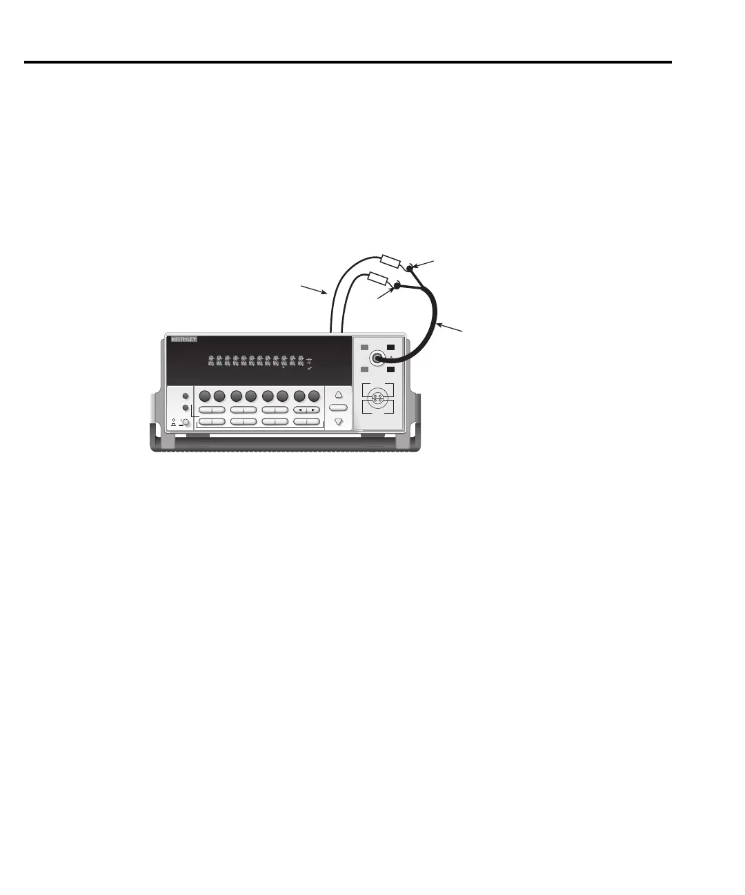
1. Connect the Model 2182 analog output to CHANNEL 1 of the front panel input jack, as
shown in Figure 2-5.
2. Send the following command to calibrate the analog output:
:CAL:PROT:DC:STEP5
Figure 2-5
Connections for analog output calibration
Programming calibration dates
Program the present calibration date and calibration due date by sending the following
commands:
:CAL:PROT:DATE <year>, <month>, <day>
:CAL:PROT:NDUE <year>, <month>, <day>
For example, the following commands assume calibration dates of 12/15/97 and 12/15/98
respectively:
:CAL:PROT:DATE 1997, 12, 15
:CAL:PROT:NDUE 1998, 12, 15
2182 NANOVOLTMETER
RANGE
!
CHANNEL 1
SHIFT
LOCAL
POWER
RANGE
SHIFT
CH1REM
TALK
LSTN
SRQ
STAT
REL FILT
4W
BUFFER
MATH
REAR
SCAN
TIMER
STEP CH2 CH3 CH4 CH5 CH6 CH7 CH8 CH9 CH10
HOLD TRIG FAST MED SLOW AUTO ERR
AUTO
HI
LO
CHANNEL 2
HI
LO
120V MAX
12V MAX
CAT I
350V PEAK ANY
TERMINAL TO CHASSIS
EXIT ENTER
DIGITS RATE
ON/OFFVALUE
TRIG
EX TRIG
STORE
RECALL
DCV1
V
1
/
V
2
MX+B
%
V
1
-V
2
DCV2
ACAL
FILT REL
TEMP
1
TEMP
2
TYPE
A
OUT
TCOUPL
DELAY
HOLD
RS232
GPIB
STEP SCAN
CAL TEST
OUTPUT
SAVE RESTR
CONFIG HALT
BUFFER
SETUP
LIMITS
Connect
2107 Low
Thermal Cable
Spade Lugs
to Clip Leads
MODEL 2182
HI
LO
Connect to Clip Leads
ANALOG OUTPUT
Jack on Rear Panel
L
SYNC
2-16 Calibration
 Loading...


