Performance Verification 1-9
5. Source positive and negative and full-scale voltages for each of the ranges listed in
Table 1-2. For each voltage setting, be sure that the reading is within stated limits.
Verifying AC voltage
Check AC voltage accuracy by applying accurate AC voltages at specific frequencies from
the AC voltage calibrator to the Model 2700 inputs and verifying that the displayed readings
fall within specified ranges.
CAUTION
Do not exceed 1000V peak between front terminals INPUT HI and
INPUT LO, or 8
×
10
7
V•Hz input, because instrument damage may occur.
Follow these steps to verify AC voltage accuracy:
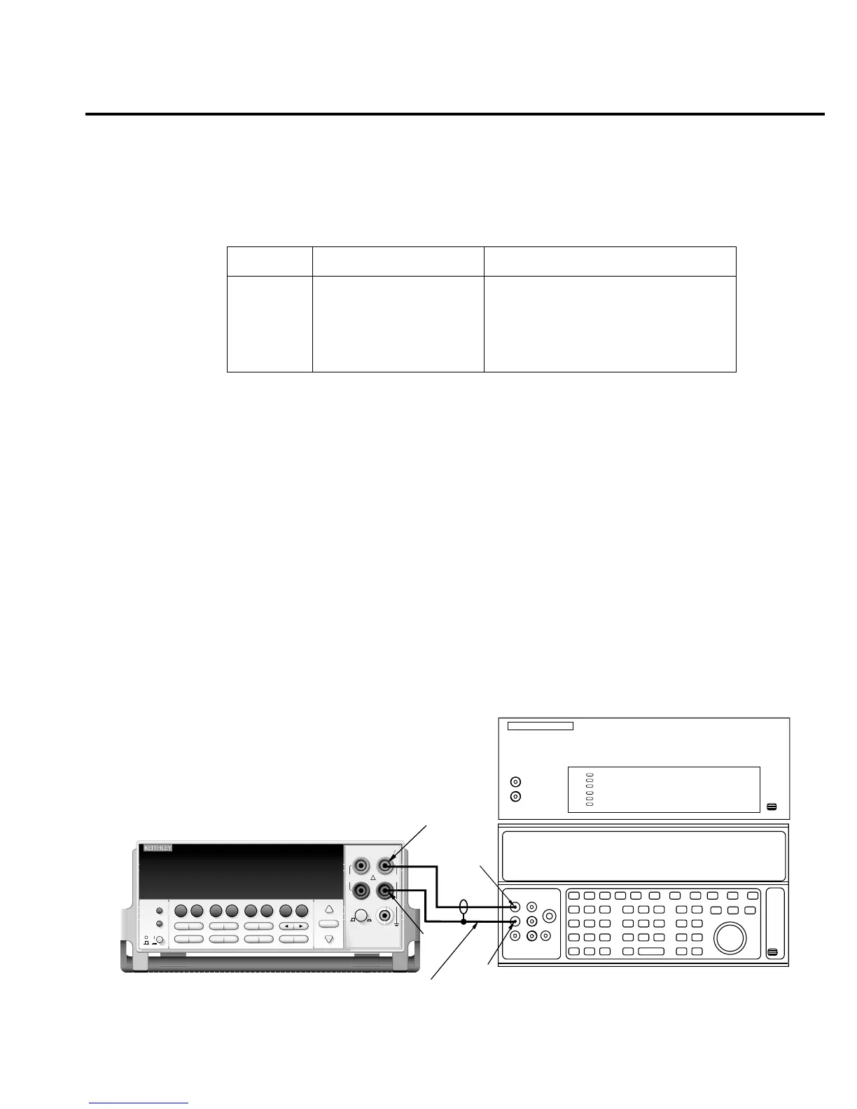
1. Connect the Model 2700 HI and LO INPUT jacks to the AC voltage calibrator as shown
in Figure 1-2. Be sure the INPUTS switch is in the FRONT position.
Figure 1-2
Connections for Model 2700 AC volts verification
Table 1-2
DCV reading limits
Range Applied DC voltage* Reading limits (1 year, 18° to 28°C)
100mV
1V
10V
100V
1000V
100.0000mV
1.000000V
10.00000V
100.0000V
1000.000V
99.9935 to 100.0065mV
0.999963 to 1.000037V
9.99965 to 10.00035V
99.9946 to 100.0054V
999.931 to 1000.069V
*Source positive and negative values for each range.
Output HI
Output
LO
Input
LO
Input HI
Calibrator (Output AC Voltage)
Shielded cable
Amplifier (Connect to calibrator)
Note: Amplifier required only
for 700V, 50kHz output.
Model 2700
Model 2700 Multimeter / Data Acquisition System
RANGE
!
F
500V
PEAK
FRONT/REAR
3A 250V
AMPS
HI
INPUT
LO
SENSE
Ω 4 WIRE
INPUTS
350V
PEAK
1000V
PEAK
AUTO
SHIFT
LOCAL
POWER
RANGE
R
EXIT ENTER
DIGITS RATE
RELFILTER
TRIG
EX TRIG
STORE
RECALL
OPEN
DCV
DCI
MATH
OUTPUT
RATIO
ACV
ACI
Ω2 Ω4
FREQ
TEMP
CH AVG
CONT
PERIOD SENSOR
LIMITS ON/OFFDELAY
HOLD
SAVE SETUP
CONFIG HALT
TYPE
LSYNC
TEST
MONITOR
STEP SCAN
OCOMP
CH-OFF CARD
CLOSE
Integra Series
RS-232
GPIB

 Loading...


