Performance Verification 1-11
Verifying DC current
Check DC current accuracy by applying accurate DC currents from the DC current calibra-
tor to the AMPS input of the Model 2700 and verifying that the displayed readings fall within
specified limits.
Follow these steps to verify DC current accuracy:
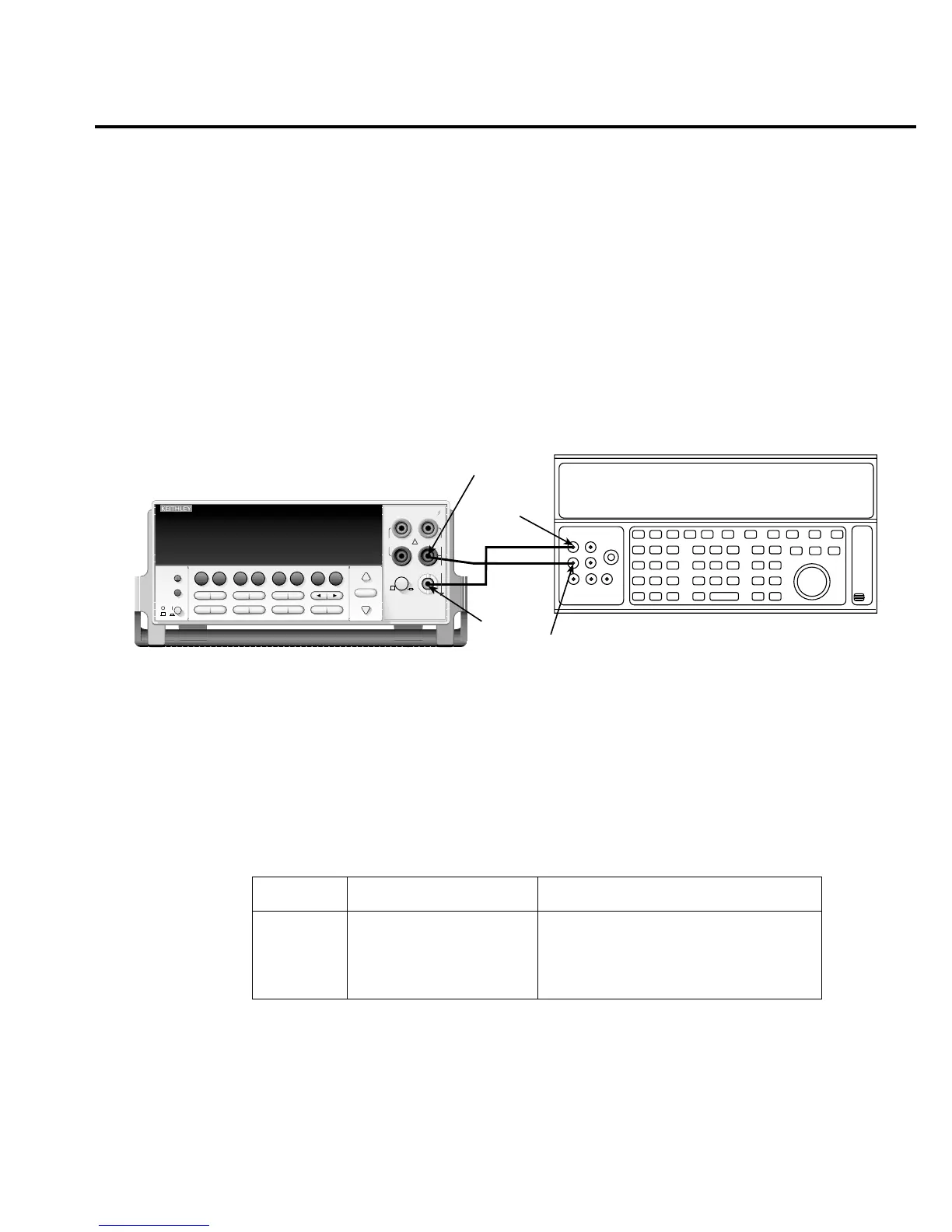
1. Connect the Model 2700 AMPS and INPUT LO jacks to the calibrator as shown in
Figure 1-3. Be sure the INPUTS switch is in the FRONT position.
Figure 1-3
Connections for Model 2700 DC current verification
2. Select the DC current measurement function by pressing the
DCI
key.
3. Set the Model 2700 for the 20mA range.
4. Source positive and negative full-scale currents for each of the ranges listed in
Table 1-4, and verify that the readings for each range are within stated limits.
Table 1-4
DCI limits
DCI range Applied DC current* Reading limits (1 year, 18°C to 28°C)
20mA
100mA
1A
3A
20.0000mA
100.0000mA
1.000000A
3.000000A**
19.89960 to 20.01040mA
99.9100 to 100.0900mA
0.999160 to 1.000840A
2.99628 to 3.00372A
* Source positive and negative currents with values shown.
** If the Fluke 5725 amplifier is not available, apply 2.2A from calibrator. Reading limits for 2.2A
input are: 2.197240 to 2.202760A.
Output HI
Output
LO
Input
LO
Note: Be sure calibrator is set for
Amps
Calibrator (Output DC Current)
normal current output.
Model 2700
Model 2700 Multimeter / Data Acquisition System
RANGE
!
F
500V
PEAK
FRONT/REAR
3A 250V
AMPS
HI
INPUT
LO
SENSE
Ω 4 WIRE
INPUTS
350V
PEAK
1000V
PEAK
AUTO
SHIFT
LOCAL
POWER
RANGE
R
EXIT ENTER
DIGITS RATE
RELFILTER
TRIG
EX TRIG
STORE
RECALL
OPEN
DCV
DCI
MATH
OUTPUT
RATIO
ACV
ACI
Ω2 Ω4
FREQ
TEMP
CH AVG
CONT
PERIOD SENSOR
LIMITS ON/OFFDELAY
HOLD
SAVE SETUP
CONFIG HALT
TYPE
LSYNC
TEST
MONITOR
STEP SCAN
OCOMP
CH-OFF CARD
CLOSE
Integra Series
RS-232
GPIB

 Loading...


