2-10 Calibration
DC current calibration
After the 1MΩ resistance point has been calibrated, the unit will prompt you to apply 10mA.
Follow these steps for DC current calibration:
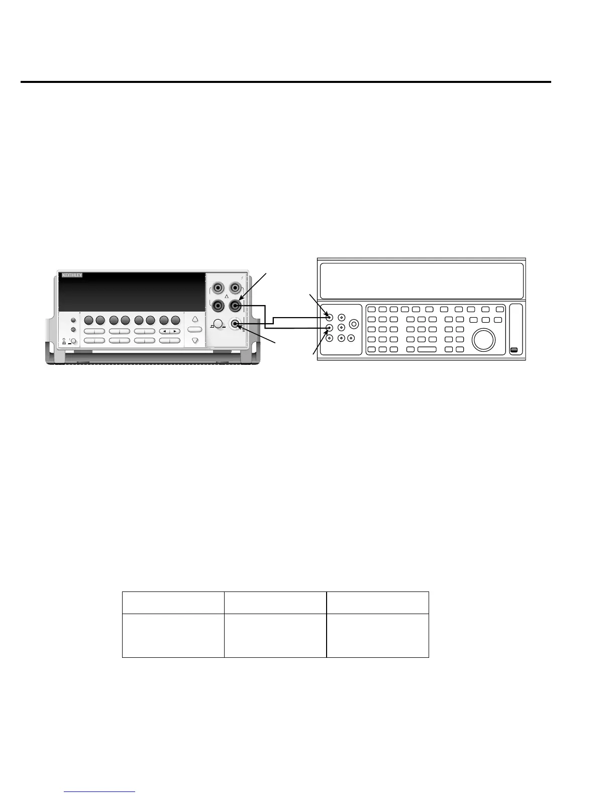
1. Connect the calibrator to the AMPS and INPUT LO terminals of the Model 2700 as
shown in Figure 2-3.
Figure 2-3
Connections for DC and AC amps calibration
2. Calibrate each current step summarized in Table 2-5. For each step:
• Set the calibrator to the indicated DC current, and make sure the unit is in
OPERATE.
• Make sure the Model 2700 display indicates the correct calibration current.
• Press ENTER to complete each step.
• Allow the Model 2700 to finish each step.
NOTE If you are performing DC-only calibration, proceed to “Setting calibration dates
and saving calibration.”
Table 2-5
DC current calibration summary
Calibration step Calibrator current Allowable range
10mA
100mA
1A
10.00000mA
100.0000mA
1.000000A
9mA to 11mA
90mA to 110mA
0.9A to 1.1A
Output HI
Output
LO
Input
LO
Note: Be sure calibrator is set for
Amps
DC and AC Current Calibrator
normal current output.
Model 2700
Model 2700 Multimeter / Data Acquisition System
RANGE
!
F
500V
PEAK
FRONT/REAR
3A 250V
AMPS
HI
INPUT
LO
SENSE
Ω 4 WIRE
INPUTS
350V
PEAK
1000V
PEAK
AUTO
SHIFT
LOCAL
POWER
RANGE
R
EXIT ENTER
DIGITS RATE
RELFILTER
TRIG
EX TRIG
STORE
RECALL
OPEN
DCV
DCI
MATH
OUTPUT
RATIO
ACV
ACI
Ω2 Ω4
FREQ
TEMP
CH AVG
CONT
PERIOD SENSOR
LIMITS ON/OFFDELAY
HOLD
SAVE SETUP
CONFIG HALT
TYPE
LSYNC
TEST
MONITOR
STEP SCAN
OCOMP
CH-OFF CARD
CLOSE
Integra Series
RS-232
GPIB

 Loading...


