1-28 Performance Verification
5. Source each of the voltages summarized in Table 1-14 and verify that the temperature
readings are within limits. Be sure to select the appropriate thermocouple type for each
group of readings. (See step 3 above.) Open Channel 1 after the test is complete.
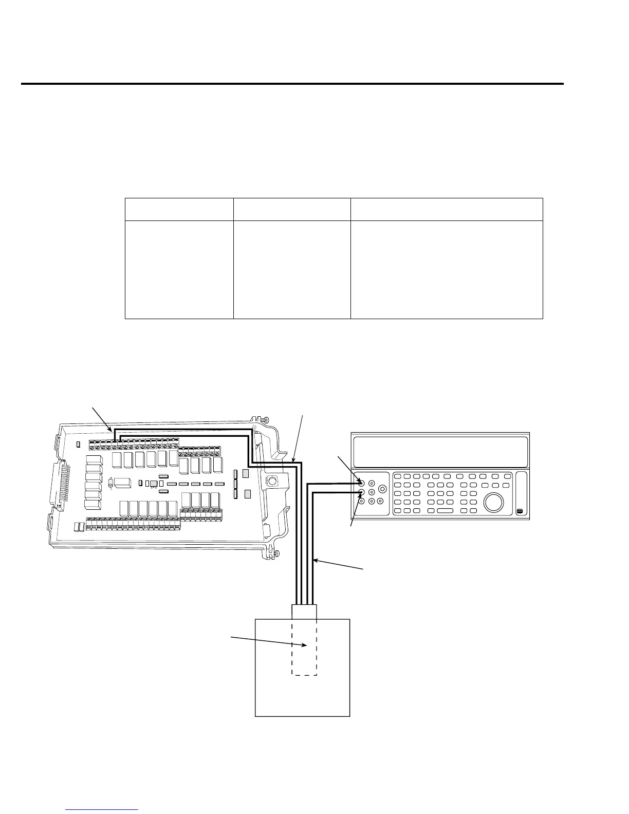
Figure 1-14
Connections for Model 7700 thermocouple temperature verification
Table 1-14
Model 7700 thermocouple temperature verification reading limits
Thermocouple type Applied DC voltage* Reading limits (1 year, 18°C to 28°C)
J
K
-7.659mV
0mV
42.280mV
-5.730mV
0mV
54.138mV
-191.0 to -189.0°C
-1.0 to +1.0°C
749.0 to 751.0°C
-191.0 to -189.0°C
-1.0 to +1.0°C
1349.0 to 1351.0°C
*Voltages shown are based on ITS-90 standard.
HLHL
AMPS
HLHLHLHLHLHL
LO
CH21 CH22 CH11 CH12 CH13 CH14 CH15 CH16
HLHLHLHL
CH17 CH18 CH19 CH20
SENSE
(OHMS, 4 WIRE)
INPUT
(V, 2 WIRE)
HLHLHLHL
CH7 CH8 CH9 CH10
HLHL
HLHL
HLHL
HLHL
INPUT SENSE
CH1 CH2
CH3
CH4
CH5
CH6
CH1
Make HI and LO
Connections
in Ice Bath
Ice Bath
Twisted
Thermocouple Wire
Output
HI
Output
LO
Calibrator (Output DC Voltage)
Notes: This setup and reading limits table
does not include errors from
ice point, thermocouple wire,
and connections.
HI and LO connections from
the calibrator and Model 7700
must be electrically isolated
from each other.
Model 7700
Low Thermal
Copper Connection

 Loading...


