4-6 Troubleshooting
Display board
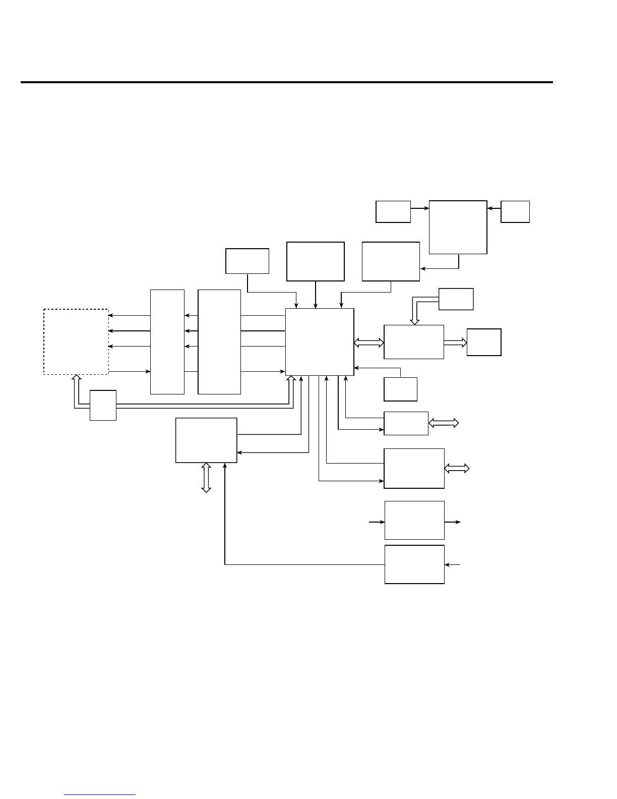
Display board components are shown in the digital circuitry block diagram in Figure 4-2.
Figure 4-2
Digital circuitry block diagram
Microcontroller
U401 is the display board microcontroller that controls the display and interprets key data.
The microcontroller uses three internal peripheral I/O ports for the various control and read
functions.
Display data is serially transmitted to the microcontroller from the digital section via the
TXB line to the microcontroller RDI terminal. In a similar manner, key data is serially sent
back to the digital section through the RXB line via TDO. The 4MHz clock for the microcon-
troller is generated by crystal Y401.
O
P
T
O
I
S
O
AT101
U150
U155
68306
µP
U135
XADTX
XADCLK
XADTS
XADRX
ADTX
ADCLK
ADTS
ADRXB
Analog
Circuitry
(See Figure 4-3)
Display Board
Controller
U401
Display
DS401
Trigger
U146, U164
Trigger
Link
TRIG IN
TRIG OUT
NVRAM
U136
ROM
U156, U157
RAM
U151, U152
XTAL
Y101
RS-232
U159
RS-232
Port
GPIB
U158, U160,
U161
IEEE-488
Bus
IN
OUT
Data IN
Data OUT
Keypad
Slot
Control
Battery
Back
Control/
Realtime Clock
U171
BAT
BT100
Y103
U127
U173
U174
Digital Output
U122, U188
U189
Digital Input
U146, U191
U192
Data Bus
Digital
I/O
Line Sync
Control
U179
U180
U181
U182
U183
U184
U186

 Loading...


