Performance Verification 1-25
Verifying resistance
Check resistance by connecting accurate resistance values to the Model 7700 and verifying
that its resistance readings are within the specified limits.
CAUTION Do not apply more than 300V between plug-in module INPUT or SENSE
H and L terminal, or between any adjacent channels, or instrument dam-
age could occur.
Follow these steps to verify resistance accuracy:
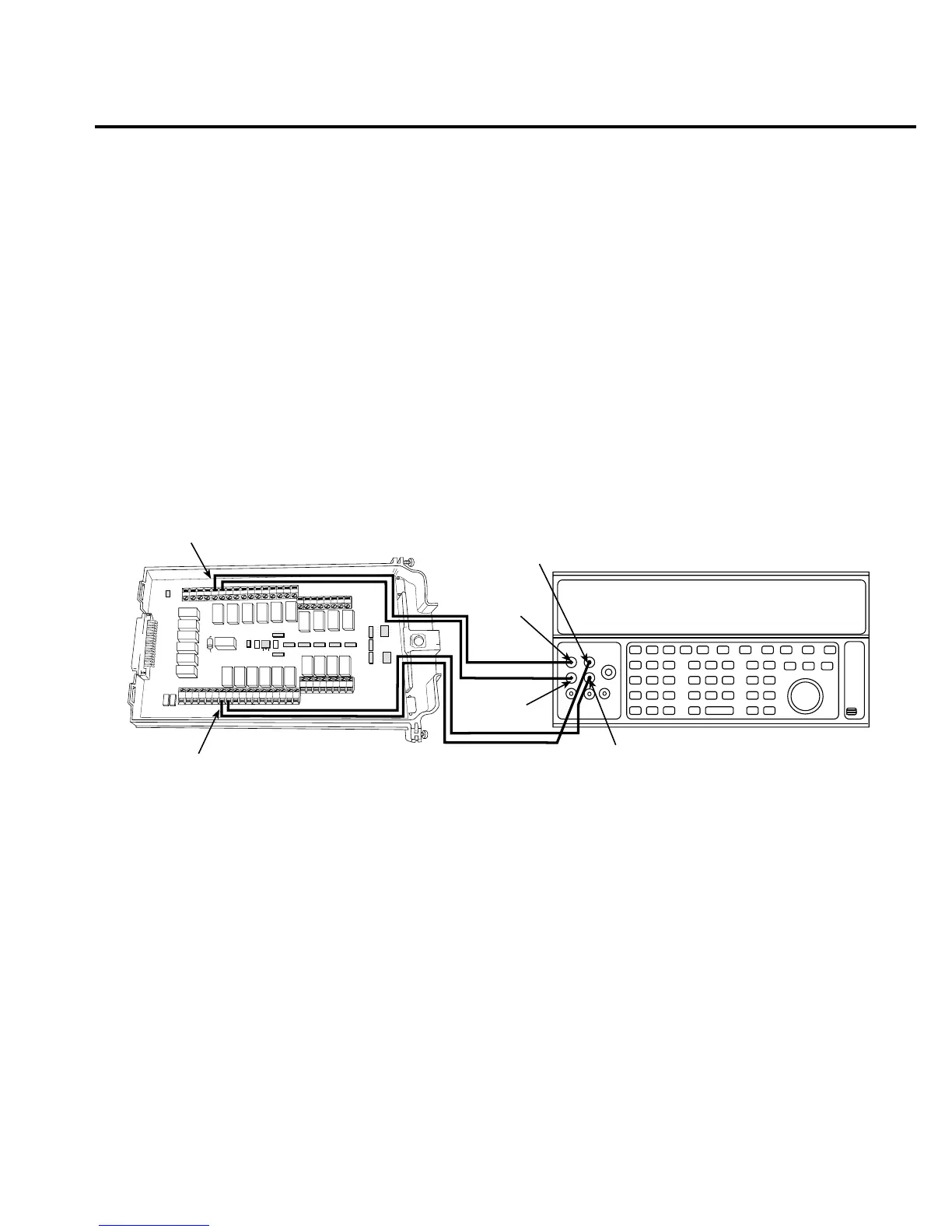
1. Using shielded Teflon or equivalent cables in a 4-wire configuration, connect the
Model 7700 CH1 H and L INPUT terminals, and CH11 H and L SENSE terminals to
the calibrator as shown in Figure 1-12.
Figure 1-12
Connections for Model 7700 resistance verification (100Ω to 10MΩ ranges)
2. Install the Model 7700 in Slot 1 of the Model 2700, then turn on the power, and allow
the unit to warm up for two hours before proceeding. Be sure the front panel INPUTS
switch is set to the REAR position.
3. Set the calibrator for 4-wire resistance with external sense on.
4. Select the Model 2700 4-wire resistance function by pressing the Ω4 key. Close Chan-
nel 1 by pressing the CLOSE key and keying in 101.
5. Set the Model 2700 for the 100Ω range, and make sure the FILTER is on. Enable
OCOMP (offset-compensated ohms) for the 100Ω range test. (Press SHIFT then
OCOMP.)
6. Recalculate reading limits based on actual calibrator resistance values.
HLHL
AMPS
HLHLHLHLHLHL
LO
CH21 CH22 CH11 CH12 CH13 CH14 CH15 CH16
HLHLHLHL
CH17 CH18 CH19 CH20
SENSE
(OHMS, 4 WIRE)
INPUT
(V, 2 WIRE)
HLHLHLHL
CH7 CH8 CH9 CH10
HLHL
HLHL
HLHL
HLHL
INPUT SENSE
CH1 CH2
CH3
CH4
CH5
CH6
CH1
CH11
Output
HI
Output
LO
Resistance Calibrator
Note: Use shielded, low-thermal cables
to minimize noise. Enable or disable
calibrator external sense as indicated
in procedure.
Model 7700
Sense HI
Sense LO

 Loading...


