4-4 Troubleshooting
Principles of operation
The following information is provided to support the troubleshooting tests and procedures
covered in this section of the manual. Refer to the following block diagrams:
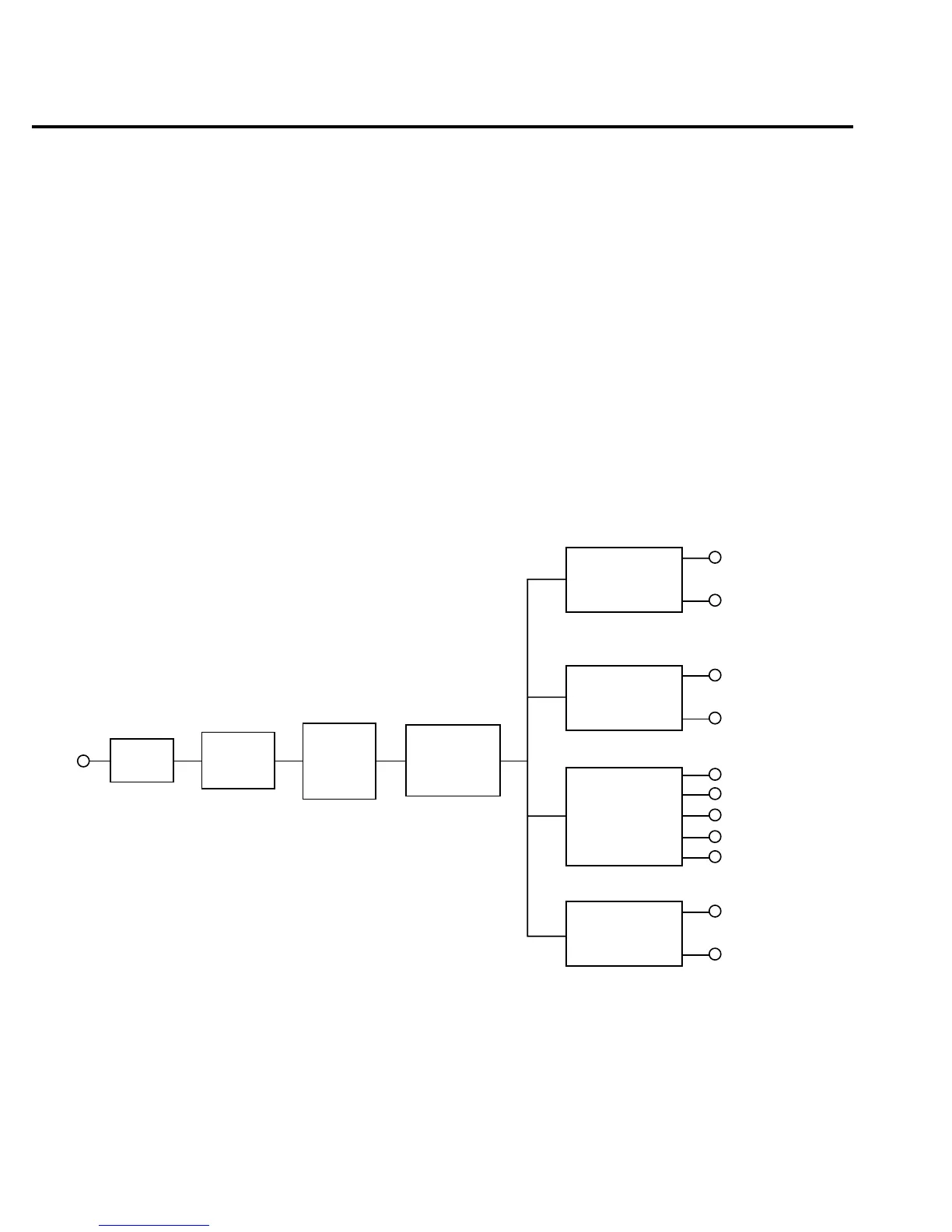
Figure 4-1 — Power supply block diagram
Figure 4-2— Digital circuitry block diagram
Figure 4-3 — Analog circuitry block diagram
Power supply
The following information provides some basic circuit theory that can be used as an aid to
troubleshoot the power supply. A block diagram of the power supply is shown in Figure 4-1.
Figure 4-1
Power supply block diagram
Fuse
Power
Switch
Line
Voltage
Select
Switch
Power
Transformer
CR103
C146
U124
CR104
C156, C175
C281, U144
CR116, CR117
C104, U101
CR102, CR115
C131, C148
U119, U125
+5VD
D Common
+37V
D Common
+15.7V
-15.7V
+5V
A Common
A Common
+18V
-18V

 Loading...


