Troubleshooting 4-13
Analog signal switching states
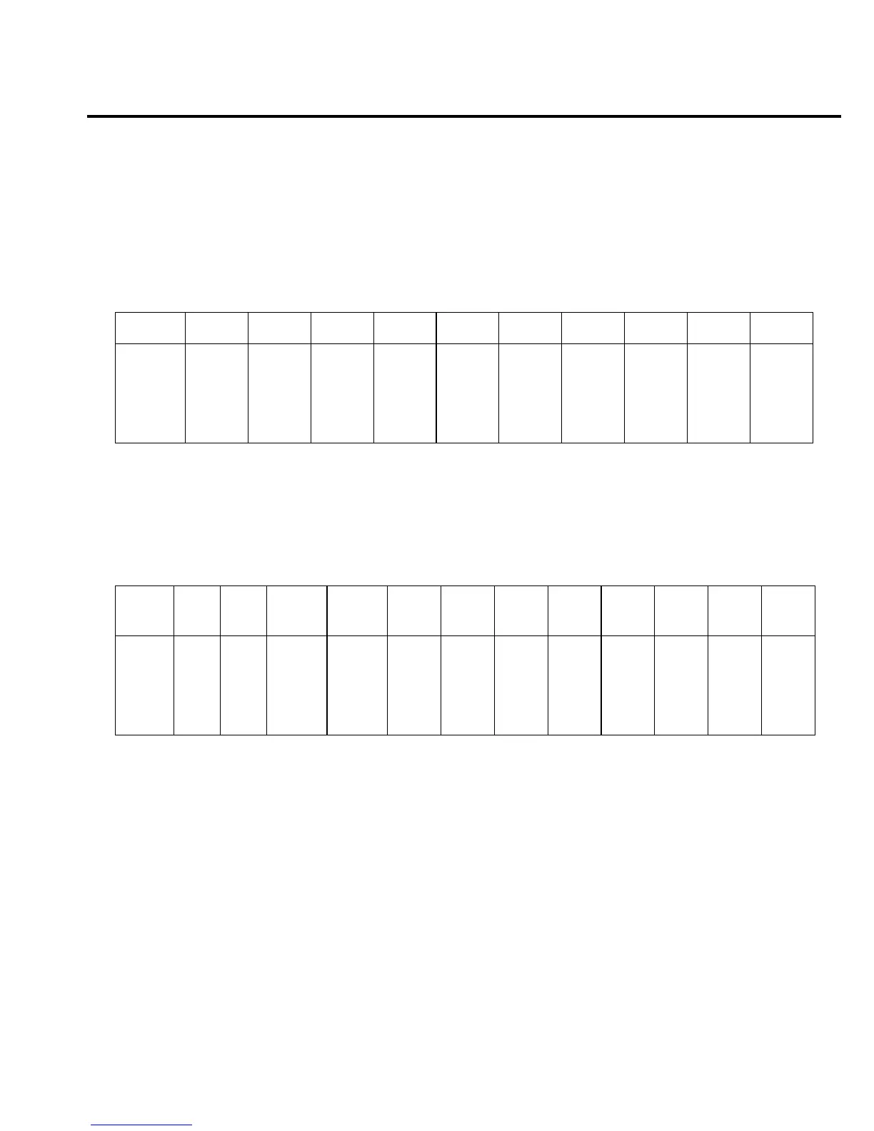
Table 4-5 through Table 4-11 provide switching states of the various relays, FETs, and ana-
log switches for the basic measurement functions and ranges. These tables can be used to assist
in tracing an analog signal from the input to the A/D multiplexer.
Table 4-5
DCV signal switching
Range Q101 Q102 Q114 Q136 Q109 K101* Q113 Q105 Q104 Q108
100mV
1V
10V
100V
1000V
ON
ON
ON
OFF
OFF
ON
ON
ON
OFF
OFF
OFF
OFF
OFF
ON
ON
OFF
OFF
OFF
ON
ON
OFF
OFF
OFF
OFF
OFF
SET
SET
SET
SET
SET
OFF
OFF
OFF
OFF
OFF
OFF
OFF
OFF
OFF
OFF
ON
ON
ON
OFF
OFF
OFF
OFF
OFF
ON
ON
* K101 set states: Pin 8 switched to Pin 7
Pin 3 switched to Pin 4
Table 4-6
ACV and FREQ signal switching
Range Q101 Q102 K101* K102*
U103
pin 8
U103
pin 9
U105
pin 9
U105
pin 8
U103
pin 16
U103
pin 1
U105
pin 1
U111
pin 16
100mV
1V
10V
100V
750V
ON
ON
ON
ON
ON
ON
ON
ON
ON
ON
RESET
RESET
RESET
RESET
RESET
RESET
RESET
SET
SET
SET
ON
ON
OFF
OFF
OFF
ON
ON
OFF
OFF
OFF
OFF
OFF
ON
ON
ON
OFF
OFF
OFF
OFF
ON
OFF
ON
OFF
ON
OFF
ON
OFF
ON
OFF
OFF
ON
OFF
ON
OFF
OFF
OFF
OFF
OFF
OFF
OFF
* K101 and K102 reset states: Pin 8 switched to Pin 9
Pin 3 switched to Pin 2
K101 and K102 set states: Pin 8 switched to Pin 7
Pin 3 switched to Pin 4

 Loading...


