7-6 Wave Functions (6221 Only) Model 6220/6221 User’s Manual
Return to Section 7 topics
Phase marker
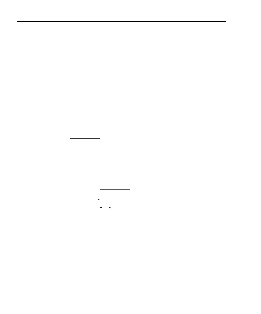
The phase marker (Figure 7-3) allows you to set a pulse marker that defines a
specific point of a waveform over a range of 0 to 360°. The phase marker signal is
a 1μs pulse that appears on the selected line of the external trigger connector
(see information on the external trigger connector in Section 8 of the Model 622x
Reference Manual for connector designations). You can also define which trigger
output line is used for the phase marker pulse (default is line 3), but you cannot
use the same line used for the external trigger output (default is 2) or the wave-
form external trigger input line (default is 0 or disabled). A 0
° marker setting for
ramp waveforms corresponds to the minimum output at the start of ramp-up. For
sine and square wave, a 0
° marker setting for square and sine waves is the zero-
crossing point.
Figure 7-3
Phase marker
Output
Waveform
High (5V)
Low (0V)
Phase Marker Pulse
Example Shows
180 Degree
Marker Setting
1ms
 Loading...