Model 6220/6221 User’s Manual Delta, Pulse Delta, and Differential Conductance 5-5
Return to Section 5 topics
Serial communications
In order to perform Delta, Pulse Delta, or Differential Conductance measure-
ments, the Model 622x must communicate to the Model 2182/2182A over the
serial (RS-232) interface. With serial communications properly configured and
connected, the Model 622x will automatically send setup commands to the
Model 2182/2182A when Delta, Pulse Delta, or Differential Conductance is
armed. When the test is started, readings from the Model 2182/2182A are auto-
matically sent to the Model 622x to be processed into Delta, Pulse Delta, or Differ-
ential Conductance readings that are then stored in the buffer.
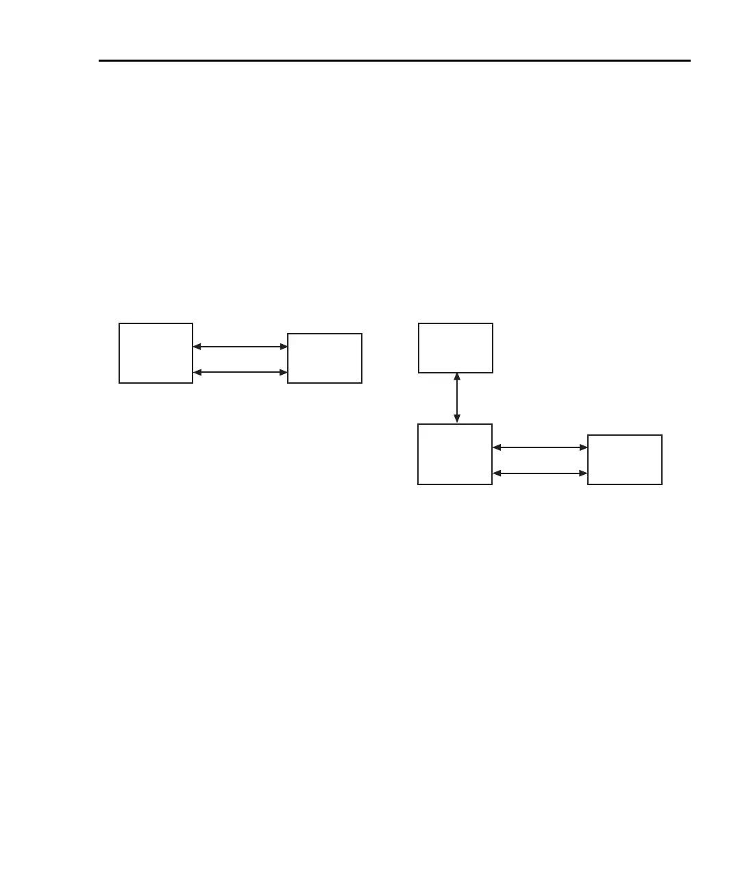
Figure 5-2
System configurations for Delta, Pulse Delta, and Differential Conductance
System connections
WARNING Before making or breaking system connections, the Models
622x and 2182/2182A, and the PC must be turned off and the
line cords must be disconnected from AC line power.
System connections depend on the system configuration being used (see
Figure 5-2). Connections for the two system configurations are explained as
follows.
Connections – stand-alone system
System connections for this configuration are shown in Figure 5-3.
RS-232 – The Model 622x communicates with the Model 2182/2182A via the
RS-232 interface. Make sure to use a null-modem RS-232 cable for this connec-
tion.
Trigger Link
Keithley
622x
Keithley
2182/2182A
Current Source
Nanovoltmeter
RS-232
A) Stand-alone system (front panel operation)
Trigger Link
Current Source
Nanovoltmeter
RS-232
B) PC control of 6220/21
PC
(null-modem)
(null-modem)
IEEE-488
or
Ethernet (6221)
RS-232 On
Keithley
2182/2182A
RS-232 On
GPIB or
Ethernet (6221)
Selected
Keithley
622x
GPIB or
Ethernet (6221)
Selected
 Loading...