10.20
Section 10
Reassembly
Install and Adjust Governor Lever
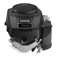
1. Install the governor lever* onto the governor
sha with the lever section up. Connect the
throle linkage using the black linkage bushing.
See Figure 10-68.
*NOTE: It is recommended that a new governor lever
be installed whenever removal is performed.
Mounting Speed Control Bracket
1. Aach the governor spring to the governor lever
and the throle lever of the speed control bracket,
in the original holes. If the holes were not marked
during disassembly, refer to the charts in
Section 5. Connect the choke linkage from the
carburetor to the actuating lever of the speed
control bracket. See Figure 10-70.
Figure 10-68. Governor Lever Installed on Shaft.
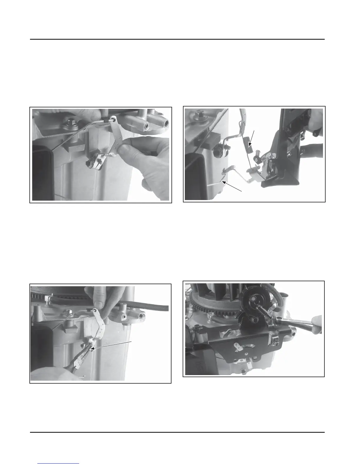
2. Move the governor lever toward the carburetor,
to the limit of its travel (wide-open throle) and
hold in this position. Do not apply excessive
pressure, flexing or distorting the linkage. Grasp
the cross sha with a pliers, and turn the sha
counterclockwise as far as it will go. See Figure
10-69. Torque the hex nut to 7.0-8.5 N·m
(60-75 in. lb.).
Rotate
Counter
Clockwise
Figure 10-69. Adjusting Governor and Linkage.
Figure 10-70. Connecting Choke Linkage and
Governor Spring.
2. Aach the speed control bracket to the
mounting locations on the engine with the M6
screws. Position the bracket as marked during
disassembly. Torque the screws to 11.0 N·m
(95 in. lb.) into new, as-cast holes or 7.5 N·m
(65 in. lb.) into used holes. See Figure 10-71.
Governor
Spring
Choke Linkage
Figure 10-71. Attaching Speed Control Bracket.